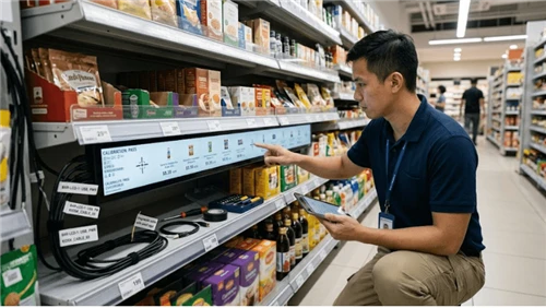
A kiosk service door tamper detection decision can look like a small mechanical or maintenance detail until the display or kiosk is installed in a real store. The production system is a chain of materials, electronics, enclosure geometry, service procedures, and field conditions. A change at one point can appear somewhere else as an optical defect, thermal fault, intermittent reset, nuisance alarm, or premature service visit. For B2B projects, the useful question is therefore not whether a component exists, but whether the complete configuration has a defined design intent and evidence that it behaves predictably.
This guide treats kiosk service door tamper detection as an engineering and procurement topic. It shows how to map the relevant system, separate failure mechanisms, define controls before tooling or rollout, collect evidence during validation, and turn the result into an RFQ and acceptance plan. Capabilities vary by model, controller, enclosure, material stack, firmware, and destination environment, so project teams should verify the exact proposed configuration instead of borrowing an unsupported number from another product.
This guide treats service-door sensing as one layer of kiosk physical-security monitoring. A tamper switch does not replace a lock, access-control process, payment-device security, or site surveillance. Exact security requirements depend on the application, threat model, and regulated peripherals.

Start With the Complete System, Not a Single Component
The fastest way to create an expensive field problem is to isolate one part of kiosk service door tamper detection from the rest of the system. Procurement sees a line item; engineering sees interfaces. Build a simple block or cross-section drawing that identifies what generates load, what carries it, what senses it, what can be serviced, and what evidence is visible after installation. The drawing does not need to be a full CAD release to be useful. Its purpose is to make assumptions visible before they become production constraints.
| System element | Role in the design | Why buyers should care |
|---|---|---|
| Mechanical lock and door structure | delay or restrict unauthorized opening | they provide physical resistance but do not by themselves create an electronic event record |
| Door-position sensor | detects whether a door, panel, latch, or cover is in its expected state | mechanical microswitches, magnetic reed sensors, Hall sensors, or latch-integrated contacts can be used depending on geometry |
| Protected wiring and I/O | carries sensor state to a controller | an exposed two-wire loop can be defeated or damaged unless routing, supervision, and failure behavior are considered |
| Local controller or embedded PC | interprets sensor changes and applies debounce/state logic | a raw contact transition must be converted into a meaningful event with time, device identity, and operating context |
| Kiosk application/service mode | distinguishes authorized maintenance from unexpected access | maintenance workflows need to suppress nuisance alarms without erasing the fact that the door was opened |
| Remote monitoring and audit store | receives, queues, and presents events to operations or security staff | network loss, clock errors, and power loss must not silently destroy the event trail |
For each element, identify the controlled document that defines it: mechanical drawing, wiring diagram, component datasheet, material specification, software state diagram, installation instruction, or service procedure. If no document owns an interface, the interface is likely to be improvised during assembly or field service. That is exactly where repeatability is usually lost.
Failure Modes: What the Symptom Can Mean and What Evidence to Collect
Troubleshooting should begin with observable evidence, not a favorite theory. Similar symptoms can come from different mechanisms, and the wrong corrective action can hide the evidence or create a second problem. The table below frames common symptoms as investigation paths rather than diagnoses.
| Observed symptom | Possible mechanism | Evidence to collect | Engineering response |
|---|---|---|---|
| Door opens with no recorded event | sensor placement, wiring, input configuration, software state, or log transport may be wrong | verify raw sensor state locally, then trace event creation, timestamping, queueing, and remote delivery | test the complete event chain instead of replacing the switch immediately |
| Repeated false tamper alarms | door flex, loose latch, vibration, switch travel, magnetic alignment, or inadequate debounce may cause chatter | compare physical door position and raw input transitions during normal use and nearby impacts | fix geometry and logic while preserving genuine detection sensitivity |
| Alarm never clears after authorized service | sensor is stuck, door is not fully latched, service mode/state machine is incomplete, or event acknowledgement is confused with physical closure | check raw closed state separately from software acknowledgement | define closure, acknowledgement, and service-mode exit as distinct states |
| Tamper event disappears when network is down | the design relies on real-time cloud delivery without a local queue | disconnect the network during a controlled door opening and inspect local event persistence | store events locally until acknowledged by the remote platform where the project requires continuity |
| Sensor can be unplugged without an alarm | the input treats open-circuit, closed-circuit, and disconnected states as equivalent | inspect wiring architecture and simulate a safe controlled disconnect | use supervision or fault logic appropriate to the project threat model |
| Authorized technicians bypass the sensor permanently | service procedure encourages taping, unplugging, or mechanically defeating the contact because access is awkward | observe real maintenance tasks and review service-mode usability | redesign access and service workflow so security controls do not conflict with routine repair |
A key discipline is to preserve the as-failed state long enough to record it. Photograph the physical condition, capture available logs, note ambient and operating state, and record the exact configuration. If the first response is to tighten hardware, reboot the computer, replace a cable, clean a filter, or disable an alarm, the project may lose the only evidence that distinguishes a design weakness from a one-off assembly error.
Design Controls That Prevent the Problem From Becoming a Field Routine
Choose a sensing technology for the door geometry
A plunger microswitch gives direct mechanical state but needs controlled travel. Reed or Hall sensing allows non-contact detection but depends on magnet position and distance. Latch-integrated sensing can reflect lock state rather than simple door position.
Useful project evidence: Sensor-selection rationale linked to the mechanical drawing and failure mode. This evidence should be tied to a drawing, BOM, software revision, or test configuration so it can be reproduced on later production units.
Place the sensor where ordinary panel flex does not mimic an opening
Long doors and thin sheet metal can move near corners. The chosen location should have repeatable alignment through production tolerance, transport, and service.
Useful project evidence: Tolerance study and sample-build open/closed margin. This evidence should be tied to a drawing, BOM, software revision, or test configuration so it can be reproduced on later production units.
Protect and document the wiring route
A sensor wire routed beside a service opening can be cut or unplugged unintentionally. The harness should be retained, identified, and included in service documentation.
Useful project evidence: Harness drawing and photo standard. This evidence should be tied to a drawing, BOM, software revision, or test configuration so it can be reproduced on later production units.
Design the event state machine, not only the electrical contact
Useful states may include closed, open, service-authorized, sensor fault, power interrupted, queued offline, and acknowledged. The exact set depends on operational needs.
Useful project evidence: Software state diagram and event schema. This evidence should be tied to a drawing, BOM, software revision, or test configuration so it can be reproduced on later production units.
Preserve evidence during network and power disruption
A security-relevant opening that occurs while offline should not vanish merely because the backhaul is unavailable. Local persistence and later synchronization can be used where required.
Useful project evidence: Offline test showing event queue and server reconciliation. This evidence should be tied to a drawing, BOM, software revision, or test configuration so it can be reproduced on later production units.
Make authorized maintenance explicit
Technicians need a documented way to enter service mode, open the door, complete work, close and verify the sensor, and exit service mode without leaving alarms disabled.
Useful project evidence: Field runbook and audit record for service-mode sessions. This evidence should be tied to a drawing, BOM, software revision, or test configuration so it can be reproduced on later production units.
Common Mistakes to Eliminate Before Pilot Build
Many failures are created by decisions that seem harmless because the unit still powers on during a short bench demonstration. Remove these habits from drawings, work instructions, and acceptance criteria before the pilot build:
- Treating a tamper sensor as a substitute for a physical lock
- Installing the switch where door flex causes intermittent contact
- Logging only "alarm on/off" without device identity, time, or service context
- Suppressing all tamper logging while a technician is in service mode
- Failing to test network loss and local event persistence
- Allowing field technicians to unplug or tape the sensor because the maintenance workflow is inconvenient
The common pattern is uncontrolled substitution. A different screw, filter, film, thermal pad, sensor, cable route, bracket, or software setting can preserve basic functionality while changing reliability. When the item affects the mechanism described in this guide, treat it as an engineering change and decide whether regression testing is needed.
Build an Acceptance Test That Reproduces the Production Configuration
A useful kiosk service door tamper detection acceptance test is not a generic power-on check. It reproduces the mounting, enclosure, player or computer load, cabling, peripherals, materials, environmental boundary, and service steps that the buyer will actually deploy. The goal is not to create an artificially severe laboratory stunt. The goal is to prove that ordinary installation and credible fault conditions lead to deterministic behavior.
| Test stage | Method | Pass evidence |
|---|---|---|
| Nominal open/close cycle | Open and close the production door through the normal latch travel. | One clear open event and one clear restored/closed state are produced without chatter. |
| Partial-open/gap test | Move the door slowly through the mechanical gap where access could begin. | Detection occurs at the project-defined physical condition and is repeatable across sample units. |
| Vibration/normal-use test | Operate touchscreen, printer door, scanner, and nearby panels without opening the protected service door. | No nuisance tamper event from expected kiosk use. |
| Sensor-disconnect test | Disconnect or interrupt the sensor circuit using the safe engineering method. | System produces the defined sensor-fault/tamper behavior rather than silently reading normal. |
| Network-loss test | Remove backhaul, open/close the service door, then restore connectivity. | Event remains available locally and synchronizes according to the agreed design. |
| Power-interruption test | Create a controlled power loss around a door-state transition. | Post-recovery state and logs are deterministic and do not falsely report a secure state without checking the input. |
| Authorized service workflow | Enter service mode, complete a representative module replacement, close the door, and exit service mode. | Maintenance is practical, alarms are correctly annotated/suppressed during authorization, and normal monitoring resumes. |
| Fleet monitoring test | Trigger events on several devices with unique identities and timestamps. | Remote console identifies the correct kiosk, event type, state, and acknowledgement history. |
Record the test setup with photographs and revision identifiers. If a later unit fails, the team should be able to answer whether it matches the tested build. A pass statement with no configuration is weak evidence because the same display or kiosk can behave differently after a panel, enclosure, PSU, player, sensor, material, or firmware substitution.
Pilot the Design Before Fleet Rollout
Run a small pilot using production hardware, production software, and the intended installation method. The pilot should exercise the day-to-day states that matter to kiosk service door tamper detection: cold start, normal operating load, scheduled operation, service access, power recovery, network recovery where applicable, and representative environmental variation. Keep the pilot long enough to reveal intermittent behavior that a short factory demonstration may miss, but do not convert pilot duration into an unsupported lifetime prediction.
Create an exception log rather than a success-only report. For each anomaly, record unit identity, time, configuration, starting state, action, visible symptom, sensor/log evidence, recovery, and whether the event was reproducible. This log becomes the basis for design changes and the field runbook. It also prevents different teams from using the same word-such as overheating, stress, aging, tamper, or failure-to describe completely different evidence.

Change Control: Keep a Known-Good Configuration Known
Once the pilot passes, freeze the interfaces that materially affect kiosk service door tamper detection. A cosmetic enclosure revision can change stiffness or heat rejection. A new adhesive or film can change optics. A replacement computer can change power density. A new sensor bracket can change switch travel. A software update can change workload or event handling. Change control does not mean refusing improvements; it means deciding which changes require a repeat of part or all of the acceptance plan.
Keep the baseline tied to part numbers, drawings, firmware/software versions, and installation instructions. When a supplier proposes an equivalent component, request the characteristics that matter to the function rather than accepting the word "equivalent" alone. For field replacement, define which items are plug-compatible and which need a regression check before the kiosk or display returns to service.
Write the Requirement Into the RFQ
A strong RFQ describes the operating scenario, required evidence, and acceptance method. It avoids unsupported design prescriptions where the supplier may have a better implementation, but it also avoids vague checkboxes such as "industrial grade," "UV resistant," "fanless," "VESA compatible," or "tamper proof." Ask what configuration was actually tested and how the supplier will keep production aligned with it.
- Define which doors, panels, cash/payment areas, and service covers require electronic detection.
- State whether the requirement is door-position detection, latch/lock-state detection, sensor-line supervision, or a combination.
- Ask the supplier to propose sensor technology and show its mechanical location/tolerance in the drawing.
- Require protected, retained, and documented sensor wiring with serviceable connectors where appropriate.
- Define event fields: kiosk identity, timestamp, open/close/fault state, service-mode context, and acknowledgement as required.
- State offline and power-loss behavior, including whether events must queue locally.
- Describe the authorized service-mode workflow and who can enable it.
- Ask how sensor replacement, door adjustment, and hinge/latch changes are regression tested.
- Include false-alarm and partial-open tests in factory/site acceptance.
- Coordinate any payment-device or regulated-area access requirements with the relevant device/compliance rules rather than assuming the kiosk sensor is sufficient.
Troubleshooting and Field Service Runbook
Field teams should have a short runbook for kiosk service door tamper detection. First verify the unit identity and current BOM/software revision. Second capture the symptom before changing the state. Third compare the physical installation with the approved photo or drawing. Fourth check available sensor or event logs. Fifth isolate the smallest change that reproduces the problem. Finally, after repair, repeat the relevant acceptance step instead of declaring success as soon as the screen or kiosk appears normal.
The runbook should also tell technicians what not to do. Do not improvise hardware lengths, bypass a sensor permanently, add dense filter media, introduce unapproved optical films, disturb thermal interface materials, or force a warped assembly into position unless an engineering instruction authorizes the change. Those actions can temporarily remove a symptom while making the fleet harder to support.
FAQ
Q: Which is better for a kiosk door: microswitch, reed switch, or Hall sensor?
A: There is no universal winner. A microswitch is direct and simple but requires mechanical travel; reed and Hall approaches are non-contact but depend on magnetic alignment. Choose based on door geometry, tolerances, environment, serviceability, wiring, and the required failure behavior.
Q: Should opening the service door always trigger a remote alarm?
A: That depends on operations. During authorized maintenance, the event should usually still be recorded even if escalation is suppressed or annotated. Security teams need to distinguish authorized access from unexpected access without losing the audit trail.
Q: Can a kiosk detect tampering when the network is offline?
A: It can if the design supports local sensing and local event persistence. The remote alert will wait for connectivity, but the opening can still be timestamped and queued. This behavior must be explicitly designed and tested.
Q: Is sensing the lock enough?
A: Not necessarily. A lock-state sensor may show "locked" even if another panel is open, and a door-position sensor may show "closed" without proving the lock is engaged. Select the state that matters to the threat model and combine signals when required.
Q: What causes false kiosk tamper alarms?
A: Common causes include door flex, worn latches, vibration, switch misalignment, excessive sensitivity, connector faults, and poor debounce/state logic. Troubleshooting should compare the raw sensor transition with the actual door position before changing software thresholds.
Final Procurement Perspective
The best way to manage kiosk service door tamper detection is to turn it from an informal feature into a controlled system behavior. Map the complete path, identify failure mechanisms, protect the interfaces that matter, validate the actual production configuration, preserve evidence, and make service/change control part of the design. This approach gives procurement, engineering, installation, and operations the same definition of "acceptable" before a volume order is placed.
For LEGOYO projects, the article should be used as a planning framework rather than as a statement that every product automatically includes every feature described. Confirm the selected model, customization, environmental requirement, and test evidence with the project team before freezing the specification.