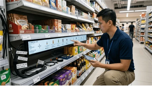
The expensive failures in unattended and retail display projects often happen at interfaces, not inside the headline component. For bar LCD touch overlay integration, the narrow question is What changes when a long, narrow bar LCD becomes interactive, and how should sensor mapping, edge accuracy, grounding, flex, bezel geometry, and service calibration be validated? This guide is written for bar-LCD product engineers, interactive-fixture designers, retail integrators, touch-controller engineers, and QA teams. It deliberately owns touch overlay integration on long narrow displays rather than generic touchscreen selection; neighboring pages should keep ownership of broader selection, networking, software, optical, or maintenance topics.
That distinction matters because the same symptom can come from hardware, configuration, installation, environment, or service history. The project should be able to name the approved state for sensor active-area registration, show how mechanical flatness interacts with it, and reproduce at least one adverse condition such as "The far end of a long sensor is offset enough that small controls become hard to select." on production-equivalent hardware. Where a numerical limit matters, use the exact model documentation, applicable standard, or an approved project requirement; do not turn a sample value into a universal claim.
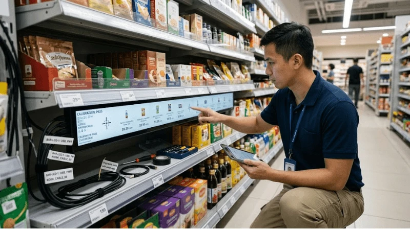
For adjacent context, use Bar LCD Display Screen, Commercial LCD VESA Mounting, Commercial LCD Airflow and Dust Control. Those resources provide broader product or integration context; the acceptance result for this article still has to be proven on the exact project configuration.
During topic research, public technical/product material from Samsung Business, LG Business, and E3 Displays was reviewed to understand category terminology and common buyer questions. Competing commercial claims are not treated as LEGOYO facts and are not linked from this publishable article. Model-specific limits, certifications, measured performance, case outcomes, and ROI must be verified against the applicable primary source before they are used in a project decision.
Define the system boundary before you compare solutions
Transparent-LCD touch and kiosk touch pages own other form factors; this page owns long narrow bar-LCD touch geometry. A clear boundary prevents two common mistakes: buying a component because a generic capability sounds right, and rejecting a component for a failure that is actually caused by the enclosure, player, site, workflow, or service process. The test object should be the production-equivalent system with the same interfaces that will exist after rollout.
Start the design review by writing three columns: what is controlled by the component supplier, what is created by integration, and what can change after handover. Then add the user-visible consequence when each item leaves the approved state. This creates a useful handoff between engineering, procurement, commissioning, and field service.
Scope-to-failure map
| Control point | What the project must define | Representative failure to challenge |
|---|---|---|
| Sensor active-area registration | Control the physical relationship between touch active area, LCD active pixels, printed mask and software coordinate space. | The far end of a long sensor is offset enough that small controls become hard to select. |
| Mechanical flatness | Limit frame twist, glass bow and adhesive stress across the long aspect ratio. | A mounting screw distorts the cover glass locally and changes touch sensitivity. |
| Edge and corner accuracy | Test small targets near both long edges and ends rather than only a center grid. | Calibration looks accurate in the center but misses promotional buttons near the end cap. |
| Grounding and EMI environment | Validate touch behavior with display power, LED drivers, shelf metal, power supplies and nearby radios in their production state. | A bench sensor is stable but becomes noisy after installation on a grounded metal shelf rail. |
| Coordinate transformation | Keep player rotation, resolution, scaling and touch orientation controlled as one configuration. | Content is rotated or scaled after an update while touch coordinates remain in the old space. |
| Service recalibration | Document replacement and calibration steps for overlay, controller, display or player without relying on manual visual guessing. | A replacement overlay is installed but the field team cannot restore the factory alignment. |
Engineering controls that deserve explicit requirements
The following controls are not generic feature-list items. Each one can change the field result for bar LCD touch overlay integration, so the approved state, evidence method, owner, and retest trigger should be visible in the project record.
Sensor active-area registration
Treat this as a change-controlled parameter whenever it can alter field behavior. Control the physical relationship between touch active area, LCD active pixels, printed mask and software coordinate space. The evidence should make it possible to distinguish a defect in sensor active-area registration from a change in mechanical flatness. A useful negative case is: The far end of a long sensor is offset enough that small controls become hard to select. Record the configuration before corrective action so the recovery does not erase the cause.
For production and service, identify the physical datum, software setting, firmware revision, material, or workflow that establishes sensor active-area registration. State which substitutions are allowed without retest and which ones invalidate the old result. This turns a one-time pilot observation into a maintainable requirement.
Mechanical flatness
A design review should connect this item to a test, an owner, and a retest trigger. Limit frame twist, glass bow and adhesive stress across the long aspect ratio. The evidence should make it possible to distinguish a defect in mechanical flatness from a change in edge and corner accuracy. A useful negative case is: A mounting screw distorts the cover glass locally and changes touch sensitivity. Record the configuration before corrective action so the recovery does not erase the cause.
Edge and corner accuracy
Put this item in the controlled requirement set before the pilot is signed off. Test small targets near both long edges and ends rather than only a center grid. The evidence should make it possible to distinguish a defect in edge and corner accuracy from a change in grounding and emi environment. A useful negative case is: Calibration looks accurate in the center but misses promotional buttons near the end cap. Record the configuration before corrective action so the recovery does not erase the cause.
For production and service, identify the physical datum, software setting, firmware revision, material, or workflow that establishes edge and corner accuracy. State which substitutions are allowed without retest and which ones invalidate the old result. This turns a one-time pilot observation into a maintainable requirement.
Grounding and EMI environment
This control needs a reproducible baseline, not an informal setup note. Validate touch behavior with display power, LED drivers, shelf metal, power supplies and nearby radios in their production state. The evidence should make it possible to distinguish a defect in grounding and emi environment from a change in coordinate transformation. A useful negative case is: A bench sensor is stable but becomes noisy after installation on a grounded metal shelf rail. Record the configuration before corrective action so the recovery does not erase the cause.
Coordinate transformation
Review this interface with production and service in the same room, because both can change it. Keep player rotation, resolution, scaling and touch orientation controlled as one configuration. The evidence should make it possible to distinguish a defect in coordinate transformation from a change in service recalibration. A useful negative case is: Content is rotated or scaled after an update while touch coordinates remain in the old space. Record the configuration before corrective action so the recovery does not erase the cause.
For production and service, identify the physical datum, software setting, firmware revision, material, or workflow that establishes coordinate transformation. State which substitutions are allowed without retest and which ones invalidate the old result. This turns a one-time pilot observation into a maintainable requirement.
Service recalibration
The supplier answer is only the starting point; the delivered configuration must make the result observable. Document replacement and calibration steps for overlay, controller, display or player without relying on manual visual guessing. The evidence should make it possible to distinguish a defect in service recalibration from a change in sensor active-area registration. A useful negative case is: A replacement overlay is installed but the field team cannot restore the factory alignment. Record the configuration before corrective action so the recovery does not erase the cause.
Failure modes: diagnose the interface, not just the visible symptom
Field teams often replace the most visible component first. That can make an intermittent problem disappear while leaving the true interface defect in place. A better fault model starts with the observable symptom, lists the two or three controlled variables that can create it, and captures evidence before reset or replacement.
| Observed failure | Primary control to inspect | Useful reproduction condition | First diagnostic action |
|---|---|---|---|
| The far end of a long sensor is offset enough that small controls become hard to select. | Sensor active-area registration | full-length grid including both ends | capture the state before changing configuration |
| A mounting screw distorts the cover glass locally and changes touch sensitivity. | Mechanical flatness | small-target test at long edges and corners | isolate the interface and reproduce on a known-good reference |
| Calibration looks accurate in the center but misses promotional buttons near the end cap. | Edge and corner accuracy | installed metal fixture with production power supplies active | compare unit/revision history before replacing parts |
| A bench sensor is stable but becomes noisy after installation on a grounded metal shelf rail. | Grounding and EMI environment | radio/network devices operating during touch test | restore the approved baseline and rerun the adverse case |
| Content is rotated or scaled after an update while touch coordinates remain in the old space. | Coordinate transformation | player reboot/resolution change followed by coordinate check | contain the user impact, then preserve logs/photos/measurements |
Do not use a single successful retry as proof of root cause. If a reboot, reconnection, cleaning step, or module swap restores service, record it as recovery evidence and keep the incident open until the team can explain why the state changed. Recurrence after the same service action is especially valuable evidence.
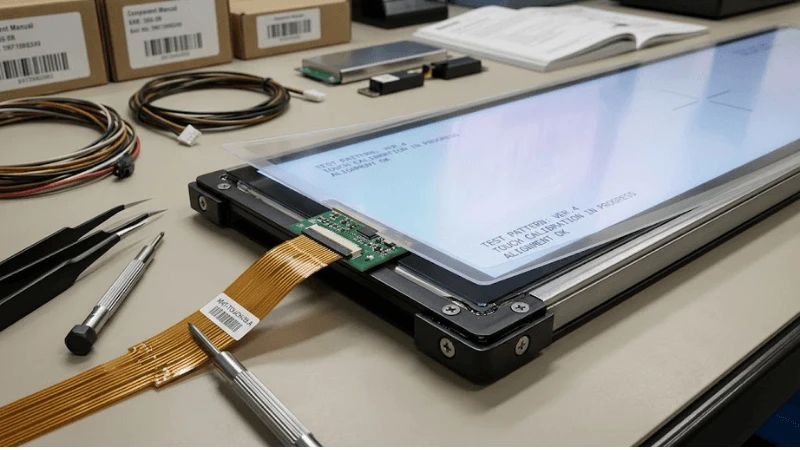
Build an acceptance test that represents the field
A factory demo should answer the project question, not merely show that the product turns on. For bar LCD touch overlay integration, include the normal condition, a tolerance edge, a service/replacement state, and at least one controlled failure. Preserve the exact unit and revision so the evidence can be reused during troubleshooting without pretending that a later substitution is identical.
Minimum test sequence
- Full-length grid including both ends
- Small-target test at long edges and corners
- Installed metal fixture with production power supplies active
- Radio/network devices operating during touch test
- Player reboot/resolution change followed by coordinate check
- Remove/reinstall touch controller or overlay and restore calibration
| Step | Condition | Main control exercised | Evidence to retain |
|---|---|---|---|
| 1 | Full-length grid including both ends | Sensor active-area registration | Pass/fail result tied to unit, revision, configuration, and test condition |
| 2 | Small-target test at long edges and corners | Mechanical flatness | Pass/fail result tied to unit, revision, configuration, and test condition |
| 3 | Installed metal fixture with production power supplies active | Edge and corner accuracy | Pass/fail result tied to unit, revision, configuration, and test condition |
| 4 | Radio/network devices operating during touch test | Grounding and EMI environment | Pass/fail result tied to unit, revision, configuration, and test condition |
| 5 | Player reboot/resolution change followed by coordinate check | Coordinate transformation | Pass/fail result tied to unit, revision, configuration, and test condition |
| 6 | Remove/reinstall touch controller or overlay and restore calibration | Service recalibration | Pass/fail result tied to unit, revision, configuration, and test condition |
Acceptance criteria should be observable. "Works normally" is weak because it does not define the task, population, environment, duration, or failure threshold. Prefer statements such as "the defined workflow completes under the approved production configuration and the specified adverse condition produces the expected state, alert, containment, or recovery." Attach measurements where the decision genuinely depends on them.
What to save in the evidence package
- Exact product model, hardware/firmware/software revision and production BOM state
- Fixture, enclosure, player, network, power, content, merchandise or peripheral configuration that affects the test
- Test method, tools and relevant environmental or operating conditions
- Pass/fail result plus photographs, logs, measurements, event records or inspection notes appropriate to the topic
- Open deviations, corrective actions, temporary controls and the person who can close them
- Retest triggers for supplier substitution, software update, site change and field replacement
RFQ questions that expose hidden integration scope
Two quotations are not comparable until they carry the same responsibility boundary. For bar LCD touch overlay integration, ask suppliers to answer with the exact quoted configuration, the evidence they can provide, and the conditions they exclude. A "yes" to a feature question is less useful than a drawing, supported-state definition, test record, service instruction, or sample that the buyer can verify.
- What touch technology and controller support the quoted bar-display geometry?
- How are sensor and LCD active areas registered during assembly?
- What mechanical flatness or support conditions are required?
- How is touch noise tested with production power/metal fixtures?
- Can calibration/configuration be exported and restored?
- Which display/player substitutions require coordinate revalidation?
Normalize the quote before comparing price
- Exact model and revision, including accessories and project options
- Included integration work versus buyer/system-integrator responsibility
- Test evidence supplied with the production configuration
- Known exclusions, tolerance limits and conditions that require a different design
- Spare/replacement strategy and configuration restoration method
- Change-notification commitment for parts or firmware that can alter the approved result
A different technical architecture is not automatically inferior. Keep the outcome and evidence requirement fixed, then allow each supplier to show how its architecture achieves them. Mandating an implementation only makes sense when an adjacent system interface genuinely requires it.
Keep the approved state alive after handover
Commissioning closes the project only if operations can recognize the same state later. Give field teams a concise baseline for sensor active-area registration, mechanical flatness, and edge and corner accuracy; include a safe recovery sequence and say which actions require engineering review. If a technician can change the result during normal service, that service step belongs in the control plan.
Fleet signals worth trending
- edge-touch miss rate
- post-service recalibration events
- EMI-related false touches
- coordinate drift after software updates
- touch-overlay replacement failures
Trend these signals by site, hardware revision, software release and last service action. One incident rarely proves a design defect, but clustering can reveal a supplier lot, configuration change, environmental condition, or maintenance practice that was invisible during pilot testing. Preserve enough history to compare "before" and "after" rather than counting tickets alone.
Retest triggers
- A supplier substitution changes sensor active-area registration or the part that establishes it.
- A firmware, driver, player, OS or configuration change can affect mechanical flatness.
- A fixture, enclosure, mounting, wiring, lighting, power, cleaning, site or workflow change alters edge and corner accuracy.
- A field replacement changes grounding and emi environment or removes a calibration/configuration dependency.
- The adverse condition "The far end of a long sensor is offset enough that small controls become hard to select." appears again in the field.
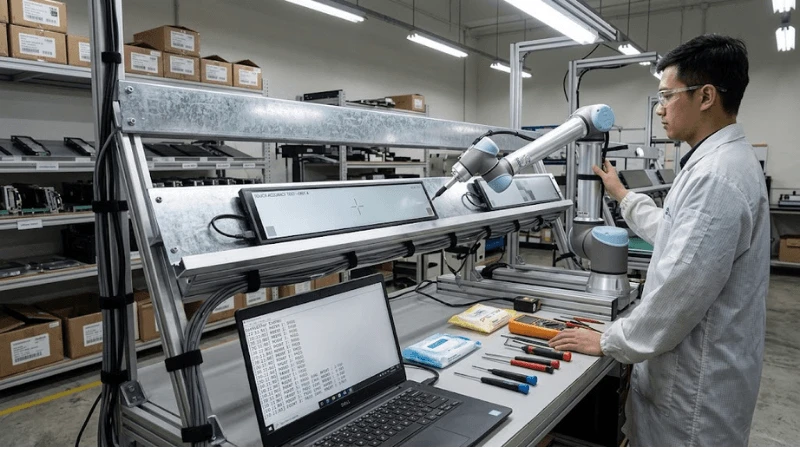
Decision gate: approve, revise, or stop
- Boundary: Can another team reproduce the approved state for sensor active-area registration?
- Interface: Is ownership clear where mechanical flatness interacts with edge and corner accuracy?
- Adverse case: Did the test include "The far end of a long sensor is offset enough that small controls become hard to select." or an equally representative failure?
- Recovery: Can service restore operation without destroying diagnostic evidence?
- Lifecycle: Is there a retest trigger when grounding and emi environment or another controlled dependency changes?
Close the review as approve, revise, or stop. If a gap is accepted temporarily, record the owner, temporary control, evidence still required, and the event that closes the exception. For related engineering boundaries, see Commercial LCD Input Signal Failover, Commercial LCD Scheduled Power Control, Commercial LCD Luminance Uniformity Testing, Stretched LCD Player, EDID, and Interface Compatibility.
FAQ
Q: What is the first thing to verify for bar LCD touch overlay integration?
A: Start with the approved baseline for sensor active-area registration and mechanical flatness. Capture the current configuration and recent service/change history before resetting or replacing parts.
Q: Can a supplier datasheet replace project acceptance testing?
A: No. Product documentation defines a starting capability boundary. Project testing proves the final combination of hardware, configuration, enclosure, site conditions, workflow and service method that will actually be deployed.
Q: Which test should be included in a pilot?
A: At minimum include full-length grid including both ends, small-target test at long edges and corners, and one adverse/service condition such as remove/reinstall touch controller or overlay and restore calibration. The objective is to expose the interface most likely to change after rollout.
Q: What should trigger a retest?
A: Retest after a component, firmware, driver, mounting, optical, electrical, environment, workflow or service change that can affect sensor active-area registration, mechanical flatness, or edge and corner accuracy.
Q: How should two supplier solutions be compared?
A: Normalize the exact configuration, inclusions, exclusions, evidence, integration responsibility, service access, replacement method and change-control commitment. Only then compare commercial terms.
Q: What evidence is most useful months after deployment?
A: Evidence tied to unit identity and revision: configuration readback, photographs, measurements, logs, test conditions, defect disposition, service history and the exact acceptance requirement. Context makes the record reusable.
Final recommendation
The strongest approach to bar LCD touch overlay integration is to make the field condition reproducible. Freeze the configuration that matters, challenge it with a realistic adverse case, preserve evidence, and make service/revision changes trigger an explicit retest. That is more useful than a long feature list because it tells procurement what to buy, commissioning what to prove, and operations what to protect.
For wider project context, return to LEGOYO Products, LEGOYO Solutions, and LEGOYO Technical Blog. When the site conditions, interfaces, intended workflow and acceptance evidence are ready for a configuration review, use Request a Quote.