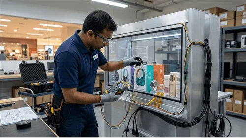
A commercial LCD can pass every video test on the bench and still fail after installation because the cable, not the display electronics, is loading the connector. A heavy HDMI adapter can twist a port. A tight cable bend can pull sideways on DisplayPort. A wall mount can move through its full travel while the service loop reaches its limit. Cleaning, transport, and maintenance can gradually work a friction-fit connector loose until the screen becomes intermittent or shows no signal.
Connector retention is therefore a load-path problem. The cable should be supported by the fixture before its mass, movement, and service forces reach the display port. The design also has to preserve enough movement for installation and maintenance, avoid over-bending the cable, and let a technician reproduce the approved routing after replacement.

Separate signal-interface choice from physical retention
HDMI, DisplayPort, USB-C, and other interfaces have different electrical and mechanical characteristics, but choosing the interface does not finish the mechanical design. The related LCD Interface Selection guide covers architecture, timing, distance, and interface compatibility. This page addresses a different question: once the interface is chosen, how should the installed cable be restrained so the connector remains seated without turning the port into a structural attachment point?
Start with the exact display, cable, adapter, mount, and enclosure configuration. Record connector orientation, available clearance, cable exit direction, nearby sheet metal, articulation path, service access, and whether the cable will be disturbed during routine operation. A rear-facing port in an open bench setup may behave very differently when installed 20 mm from a wall plate or inside a thin retail housing.
Trace the mechanical load from cable to fixture
Every installed cable has mass and stiffness. It may also experience pull, torsion, vibration, or repeated movement. The useful design question is: where is that load transferred before it reaches the display connector?
A controlled route usually has three functional regions:
- connector region: enough clearance for the plug body, latch or release feature, and the first portion of cable;
- strain-relief region: a clamp, clip, tie mount, bracket, cable saddle, or other fixture feature that carries cable load without crushing the cable;
- service region: the managed extra length needed for installation, articulation, removal, or replacement.
The display port should not be the first point that arrests a hanging cable. Likewise, the strain-relief feature should not be placed so close that it forces an immediate sharp bend at the plug. Exact minimum bend radius, clamp force, and connector retention requirements must come from the selected cable, connector, and equipment documentation rather than a generic LCD rule.

Support adapters and couplers as separate masses
Adapters are a common source of hidden connector load. A short HDMI-to-DisplayPort adapter, right-angle coupler, extender transmitter, or inline conversion device can create a lever arm that is much heavier and stiffer than a simple plug. If the adapter hangs directly from the display, cable movement can multiply the bending moment at the port.
Where the installed topology requires an adapter, decide whether it needs its own bracket or supported cable section. Keep the adapter accessible enough to identify and replace, but prevent it from swinging or resting against a fan, cover, wall, or moving mount. If an adapter is optional, compare the cleaner architecture against the adapter-based one before freezing the enclosure.
Do not assume a right-angle adapter automatically improves reliability. It can solve clearance while introducing a new mating interface and a different load direction. Validate the final part number and orientation in the actual enclosure.

Design the first bend before choosing the cable length
A cable can be long enough and still be badly routed. The first bend after the plug often determines whether the connector is pulled sideways. Check the route with covers installed, the mount at every approved position, and the service panel open where applicable.
Look for four failure conditions:
- the cable is forced into a tight bend immediately behind the connector;
- the enclosure cover presses on the plug or cable jacket after closing;
- the cable rubs a sharp sheet-metal edge or screw point;
- the cable can fall into a fan, hinge, slider, or other moving mechanism.
A grommet or edge protector can reduce abrasion at a penetration, but it does not replace strain relief. Conversely, a tight tie wrap that visibly deforms the cable jacket is not good strain relief. The restraint method has to hold the cable while preserving the cable construction specified by its manufacturer.
Size the service loop for a real maintenance task
"Leave extra cable" is not a service-loop specification. Too little extra length forces the technician to work against the connector. Too much can fall into airflow paths, become pinched by a cover, or be re-routed inconsistently after service.
Define the maintenance action first. If the display must slide forward before the connector can be reached, the loop needs enough controlled movement for that travel. If the screen is replaced from the front, the technician may need to support the panel while disconnecting the harness. If the connector can be reached directly from a service door, a smaller managed loop may be preferable.
Mark or photograph the approved loop position. Where practical, use routing features that naturally return the cable to that position instead of depending on memory. The related Commercial LCD Panel Replacement guide explains why a replacement panel or controller should be checked against the complete interface and service path rather than treated as a drop-in part.
Check every articulated position, not just the normal viewing angle
Tilting, swiveling, sliding, or pull-out mounts change the cable path. A route that is relaxed at the viewing position can become taut at the service limit. The opposite can also happen: the cable has enough length to move, but it forms a loop that is trapped when the mount returns.
Move the assembly slowly through every permitted position while observing the cable near the connector, strain-relief point, mount joints, and enclosure edges. The cable should not become the travel stop. The connector should not rotate in the port. A retained connector should also remain releasable with the intended service tool or finger access.
If the mount or enclosure is changed after acceptance, repeat this motion check. A bracket revision can move a strain-relief point by only a small distance yet completely change the cable loading at full travel.
Plan for transport and installation disturbance
Public displays are often wired before final positioning. Transport vibration, lifting, wall mounting, cabinet closure, or installers pulling excess cable through a conduit can disturb a connector that was stable during factory test. Decide which connections are shipped mated, which are connected on site, and which are inspected after the display reaches its final position.
If the cable passes from the display into the building or furniture, keep installation pulling forces away from the display port. Provide an intermediate retention point or service termination where the site cable can be managed independently from the short equipment lead.
After final mounting, inspect that the plug is fully seated, any intended latch or locking feature is engaged, the supported cable path matches the approved route, and no cover or trim piece has introduced pressure on the connection.
Use locking features only when the service model supports them
Some connector families or cable assemblies provide latches, screws, clips, locking shells, or accessory retention hardware. These features can reduce unintended disconnection, but they must match the exact connector and equipment design. An improvised restraint that blocks the release mechanism can turn a simple cable replacement into port damage.
Where a lock is used, verify three states: normal operation, intentional service removal, and replacement. A field technician should be able to identify how the connector is released without pulling harder on the cable. Keep the retention hardware in the service documentation and spare-parts list if it is not a standard part of the cable assembly.
Diagnose intermittent video before replacing the display
Connector problems often appear as symptoms that look electronic: brief blackouts, a no-signal message, resolution renegotiation after movement, or a fault that disappears when the cabinet is opened. When the symptom correlates with mount movement, cable touch, vibration, or recent service, inspect the physical connection early.
| Symptom | Physical check | Isolation step |
|---|---|---|
| Image drops when mount moves | Look for taut cable, rotating plug, or trapped loop | Test with the display fixed in place and a supported known-good cable |
| No signal after service | Verify full insertion, selected input, adapter seating, and strain relief | Connect a known-good source/cable directly where safe and practical |
| Intermittent fault after transport | Inspect plug seating and any heavy inline adapter | Restore the approved route before replacing hardware |
| Fault appears after enclosure closes | Check cover pressure and bend at the plug | Observe cable position through the closing sequence |
The broader LCD Display Troubleshooting guide helps separate connector faults from power, source, timing, thermal, and panel problems.

Acceptance test: prove the connection through use and service
Acceptance should reproduce the events that can disturb the installed cable. Use the production display, final mount, cable family, adapters, enclosure, and source. Record the exact configuration so the test can be repeated after a substitution.
- Verify stable video in the normal operating position.
- Inspect plug seating and the complete supported cable route.
- Move the display or service mechanism through every approved position while video is active.
- Apply only the controlled handling expected during normal service; do not use destructive pull tests on installed equipment unless a qualified procedure requires them.
- Open and close covers or doors that can affect the cable path.
- Perform a representative disconnect/reconnect using the intended service access.
- Return the cable to the documented route and verify stable signal again.
- Repeat the affected checks after transport, mount changes, cable substitutions, adapter changes, or display replacement.
For interface-level standards and connector families, consult the relevant source specifications and the VESA standards resources where DisplayPort standards apply. Mechanical acceptance still has to be proven on the actual commercial installation.
Reliable connector retention means the fixture carries the cable load, the display port only performs its intended electrical/mechanical mating function, and service can be completed without introducing a new stress path. For the broader commercial display family, see Bar LCD and Commercial LCD Displays.