An IP rating on a kiosk drawing can create false confidence if the project does not define what portion of the enclosure was tested. The front touch surface may be sealed while a printer slot, service door, ventilation opening, cable entry, speaker grille, or base joint remains exposed. Even when a component carries its own ingress rating, the completed kiosk can lose that protection after integration.

This guide explains how to specify front-bezel sealing, gasket design, drainage, cable entry, and acceptance evidence for a kiosk display category project. It does not assign an IP rating to any LEGOYO product. If a project requires a formal rating, the exact configuration and applicable test scope should be verified using the relevant standard and qualified test evidence. The article's purpose is to help buyers turn "waterproof kiosk" into an engineering boundary that can be drawn, built, inspected, and tested.
Start by Drawing the Protected Boundary
Mark the enclosure surfaces that are expected to resist ingress and the openings that intentionally cross that boundary. A kiosk may need only a sealed customer-facing bezel in a supervised indoor location, or it may need a much broader enclosure boundary for outdoor exposure. Those are different products even if the front appearance is similar.
On the drawing, identify the touch/display window, front-panel seams, service doors, locks, vents, fans, speakers, payment device, printer outlet, scanner window, camera opening, cable glands, power inlet, base joint, and any mounting penetrations. For each, state whether it is inside or outside the claimed boundary and what method preserves the boundary.
| Potential ingress path | Design control to review | Acceptance evidence |
|---|---|---|
| Touch/display perimeter | Gasket, bonded seal, compression frame, flat mating surfaces | Drawing, material spec, compression/assembly check |
| Service door | Continuous seal, latch spacing, hinge geometry, compression uniformity | Door-gap inspection and repeat closure test |
| Cable entry | Rated gland or sealed feedthrough appropriate to cable and hole | Installed-cable inspection and pull/strain check |
| Ventilation | Protected vent architecture, baffle, membrane, or boundary relocation | Airflow and ingress test on final configuration |
| Printer/payment openings | Architectural separation, internal drainage, or protected module design | System test with production peripheral |
| Base/anchor points | Sealed hardware or boundary kept above floor joint | Installation drawing and site acceptance check |
Front-Bezel Sealing Depends on Compression, Not Just Gasket Material
A gasket only seals when the mechanical stack compresses it within the range intended by the gasket and joint design. Too little compression leaves leak paths. Excessive compression can permanently deform the material, bow the bezel, load the touch stack, or make service reassembly inconsistent. The fastener pattern, bezel stiffness, surface flatness, corner geometry, and gasket joint all affect the result.
Define the gasket material, cross-section, placement, joining method, surface finish, and assembly process in controlled documents. Avoid field instructions such as "tighten until sealed." If the bezel uses clips or adhesive instead of screws, the retention system still needs to maintain the seal across temperature, service cycles, and normal mechanical loads.
Keep Water Management Separate From Electronics
Not every opening can be hermetically sealed. Printers need paper exits; speakers need acoustic paths; some high-power kiosks need airflow. In those areas, good enclosure design often manages water by geometry: overhangs, labyrinths, drip edges, internal shields, drainage paths, and the location of sensitive electronics. The goal is to keep credible water paths from reaching energized assemblies or pooling where they can cause corrosion.
Drainage must remain functional after installation. A drain hole blocked by floor sealant or a kiosk installed at the wrong tilt can defeat a design that worked in a bench fixture. Document required orientation and clearances in the site installation drawing.
Treat Cable Entries as Part of the Final Configuration
A cable gland or sealed feedthrough has to match the actual cable diameter and installation method. Running two small cables through a gland intended for one larger cable can create a leak path. Cutting a larger hole during field installation and filling the gap with improvised sealant destroys repeatability.
Freeze the power, network, antenna, and peripheral entry plan before formal ingress validation. If field teams may add an antenna, scanner, or payment cable later, provide a defined spare entry method or require a controlled modification kit. A formal enclosure claim should not silently survive an uncontrolled new hole.
Coordinate Sealing With Thermal Design
Improving ingress protection can reduce natural airflow and make thermal design harder. Do not seal vents during a late-stage waterproofing fix without repeating thermal validation. The fanless kiosk thermal design guide is relevant here because heat paths, component derating, and enclosure boundary are coupled decisions.
For a fan-cooled kiosk, decide whether the fan moves outside air through the protected electronics volume or whether heat is exchanged across a boundary. Filters can reduce particulate ingress but add pressure drop and maintenance needs. Membrane vents can equalize pressure in some designs but have their own airflow and placement constraints. The correct architecture is application-specific.
Touch and Optical Performance Must Survive the Seal
A sealed bezel can change the mechanical stack around the touch panel. Uneven clamp load may create visible pressure effects on the LCD or change the edge behavior of a projected-capacitive sensor. A thicker cover, bonding change, or gasket lip can also alter optical appearance. Re-run touch accuracy, edge target, multi-touch where required, and visual checks after the production sealing stack is assembled.
If the kiosk includes payment, scanner, or other sensitive electronics near the front surface, combine the sealing review with the grounding principles in the kiosk ESD and grounding guide. The sealed front should not force cable routing or shield termination into an improvised path.
Specify the Claim Precisely: Front Only, Enclosure, or Installed System
Many products legitimately state a front-panel ingress rating because the exposed front is sealed while the rear is intended to remain inside another cabinet. That can be appropriate for an open-frame touch monitor integrated into a kiosk. It becomes misleading only when the project treats the front rating as if the whole freestanding kiosk has the same protection.
Write the claim exactly as it will be used in procurement and marketing. State the tested orientation, boundary, installed accessories, and whether cable entries and peripherals were included. If a third-party test is required, make sure the report identifies the same configuration the buyer will receive.
Build an Acceptance Plan Around the Production Assembly
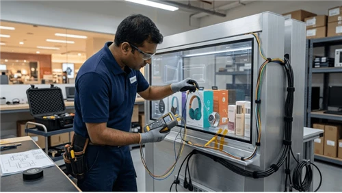
Formal IP testing should follow the applicable test method for the claimed rating when required. Before that formal stage, engineering can run controlled leak-path and assembly checks to eliminate obvious design problems. Use production seals, real cables, actual service doors, and final peripheral apertures. A prototype with taped holes does not qualify the released enclosure.
| Acceptance stage | Purpose | What to record |
|---|---|---|
| Drawing review | Confirm protected boundary and every penetration | Released drawing revision and boundary markup |
| Pilot assembly | Verify gasket placement, compression, cable entries, door closure | Photos, torque/process record, defect log |
| Engineering ingress screen | Find obvious leak paths before formal test | Water/dust path observations and corrective actions |
| Thermal regression | Confirm sealing changes did not create overheating | Temperature evidence on production configuration |
| Touch/optical regression | Confirm bezel load and cover stack remain acceptable | Touch map, visual patterns, representative UI test |
| Formal test if required | Verify claimed ingress rating on exact configuration | Qualified report tied to model/BOM/revision |
| Site acceptance | Verify installation preserves drains, glands, doors, and orientation | Installer checklist and photos |
Design for Service Without Sacrificing the Seal
A kiosk that passes once at the factory can lose protection after the first field repair. Gaskets can twist, become contaminated, take a compression set, or be omitted. Door latches can be adjusted incorrectly. Cable glands can be loosened and not re-tightened. Make the service procedure restore the same mechanical state as production.
The kiosk service door tamper guide provides adjacent service-door thinking: maintenance access should be observable and repeatable. For ingress protection, add seal inspection and replacement criteria to the service kit. If a gasket is single-use or must be replaced after opening, state that explicitly in the parts and work instructions.
Common Procurement Mistakes
- Accepting "IP65" without asking whether the rating applies to the front surface, a component, or the full kiosk.
- Using a rated touch monitor inside an enclosure and assuming the final kiosk inherits the monitor rating.
- Changing cable holes or peripheral cutouts after the ingress test.
- Adding sealant as a production workaround without controlling material, surface preparation, cure, and service replacement.
- Ignoring drainage orientation in the site installation drawing.
- Sealing ventilation late in the project without thermal regression.
- Passing a new unit but never checking sealing after a normal service-door cycle.
RFQ Questions for Kiosk Ingress Protection
- What exact IP claim is proposed, and what physical boundary does it cover?
- Which standard and test method apply to that claim?
- Was the test performed with the same display, touch stack, printer, payment device, vents, and cable entries as the quoted kiosk?
- How are gasket material, compression, joining, and replacement controlled?
- Which penetrations are allowed during site installation and how are they sealed?
- How does the enclosure manage water around printer slots, speaker openings, and ventilation?
- What thermal regression was performed after the sealing design was frozen?
- What service steps are required to restore the sealed boundary after maintenance?
FAQ
Q: Does an IP65 touch monitor make the whole kiosk IP65?
A: No. A component rating applies to the component and test boundary stated by its manufacturer. The finished kiosk includes seams, doors, cable entries, vents, peripherals, and installation details that require their own system-level evaluation.
Q: Can a kiosk be sealed and still use fans?
A: Yes, but the architecture must define how airflow and the protected boundary interact. Some designs protect the airflow path; others isolate the electronics and exchange heat differently. Any change to ventilation should be validated for both ingress and thermal performance.
Q: Should gaskets be reused after service?
A: That depends on the gasket material and joint design. The service procedure should state whether inspection, cleaning, repositioning, or replacement is required. Do not leave the decision to technician judgment without criteria.
Q: What is the most important document for a waterproof kiosk project?
A: A protected-boundary drawing is one of the highest-value documents because it shows exactly where the claim applies and how every opening crosses or stays outside that boundary. Pair it with the released BOM and test report for the exact configuration.
Map Gasket Compression Around Doors, Corners, and Hinge Zones
A continuous gasket does not guarantee continuous sealing pressure. Corners can bridge, long panels can bow, latch spacing can create low-compression zones, and a hinge can over-compress one side while the opposite edge barely contacts. During mechanical qualification, inspect the full seal path rather than checking only that a gasket is present. Compression-sensitive film, witness marks, controlled feeler methods, or other suitable engineering techniques can help reveal uneven contact when appropriate to the design.
Door stiffness and latch geometry are part of the seal. If a service door needs excessive force to close, technicians may leave it partially latched; if it closes too easily after the gasket takes a permanent set, the original sealing condition may no longer exist. Define acceptable closure and latch behavior together with the gasket material and installed geometry. Changes to sheet-metal thickness, fasteners, hinge position, or door flatness should trigger a sealing review even if the gasket part number does not change.

Control Cable Entries, Base Penetrations, and Site Work
Many kiosk ingress failures are created after factory testing. Installers drill an unplanned cable hole, omit a gland insert, route a conduit so water can run toward the enclosure, or leave a floor/base interface outside the tested configuration. The site drawing should distinguish factory-sealed penetrations from field-installed entries and specify the approved method for each. If a cable must cross the protected boundary, the gland, grommet, connector, or conduit interface becomes part of the ingress design.
Pay particular attention to the lowest points of the enclosure. Water management should not depend on a cable loop, drain opening, or base seam behaving differently from the installed orientation. If the kiosk is anchored to a plinth or floor, define whether the base interface is inside or outside the claimed protected volume and what site sealing is required. The acceptance checklist should verify those items after installation rather than assuming factory evidence covers field modifications.
| Boundary feature | Factory control | Site acceptance question |
|---|---|---|
| Front bezel gasket | Released material, joint design, compression geometry | Is the bezel seated evenly with no visible distortion or open joint? |
| Service door | Hinge/latch alignment and seal path | Does the door fully latch and reproduce the qualified compression? |
| Cable gland / conduit | Approved entry hardware and diameter range | Does the installed cable match the sealing insert and orientation? |
| Printer / speaker opening | Defined labyrinth, membrane, or protected-zone architecture | Is the production peripheral configuration the one that was qualified? |
| Base / anchor interface | Drawing defines protected boundary and drainage | Were unapproved holes or sealants introduced during installation? |
Perform a Post-Service Reseal Check
Maintenance changes the risk profile because seals are disturbed intentionally. A service instruction should identify which gaskets are reusable, which must be replaced, how mating surfaces are cleaned, how cables must be repositioned, and how latches or fasteners are tightened. If a seal can be pinched, rolled, contaminated, or installed backward, include a visual reference that makes the correct condition obvious to the technician.
The service-door controls in the kiosk service door tamper guide can complement ingress procedures: a door-open event can provide useful maintenance context, but it does not prove that the seal was restored correctly. The final service step should include a physical reseal inspection and any project-specific check required by the qualified design.
Re-Test Ingress After Thermal or Ventilation Changes
Ingress and thermal design are coupled. Adding a fan, changing a filter, enlarging a vent, relocating a heat exchanger, or sealing a gap can alter both water paths and component temperature. A change that improves one requirement can weaken the other. Treat the protected-boundary drawing and thermal model/test plan as linked configuration items.
When the enclosure changes, repeat the relevant tests from the fanless kiosk thermal design guide qualification and review grounding continuity against the kiosk ESD and grounding guide architecture. This prevents a late sealing modification from creating an overheated controller, a poorly bonded metal panel, or an airflow path that bypasses the intended water-management features.
Make the IP Claim Configuration-Specific
An IP statement should identify the enclosure configuration and boundary that were tested. If the finished kiosk has optional printers, payment terminals, scanners, speakers, cameras, vents, or service doors, determine whether each option is included in the tested configuration. Do not extend a front-panel or component claim to the complete kiosk unless the complete system has the applicable evidence.
For deployment documentation, keep the released boundary and service controls with the product catalog configuration record, use contact LEGOYO for enclosure questions, and document the responsible supplier context via about LEGOYO. This is more defensible than treating "waterproof" as an adjective detached from the exact kiosk build.
Final Procurement Perspective
Kiosk ingress protection is a system property created by geometry, seals, cable entries, peripheral architecture, drainage, thermal design, installation, and service discipline. Define the boundary first, then validate the released configuration instead of relying on a component badge. Project teams can review the broader self-service terminal solution, product catalog, and display solutions overview resources, use LEGOYO technical blog for adjacent reliability topics, and use request a project quotation to specify the exact enclosure boundary and acceptance evidence required for the deployment.