A kiosk can ship with a capable Wi-Fi or LTE module and still perform poorly after the electronics are installed behind steel panels. The radio module, antenna, coax cable, ground reference, display electronics, payment devices, service door, and installation site all influence the usable RF path. A lab test with an open chassis is therefore weak evidence for a production self-service terminal solution deployment.
This guide explains Wi-Fi and cellular antenna placement for a kiosk display category with a metal enclosure. It is written for OEM engineers, system integrators, retail IT teams, and procurement managers who need repeatable connectivity rather than a checkbox that says "Wi-Fi/LTE supported." Exact signal thresholds, antenna gains, bands, and certifications remain model- and region-specific; the article focuses on design method and acceptance evidence.
Treat the Metal Enclosure as Part of the RF System
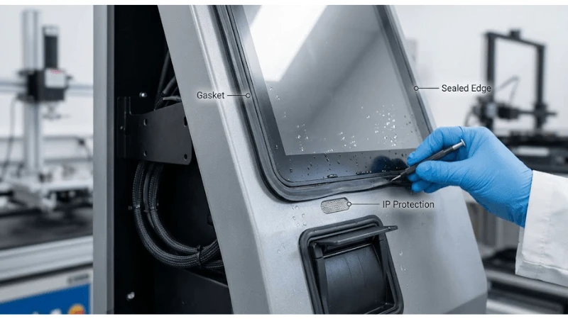
Metal panels can shield, reflect, detune, or shadow radio energy. An antenna that works on the bench may lose coverage when placed behind a closed service door or next to a grounded display frame. Slots, glass windows, plastic bezels and ventilation openings can create more favorable paths, but they should not be treated as accidental antennas. Choose the placement deliberately and validate the final enclosure.
The mechanical drawing should identify the antenna keep-out region, nearby conductive structures, cable route, connector orientation, and service-access requirements. This prevents a later bracket, speaker, cable bundle, or payment module from occupying the RF clearance zone.
Choose Antenna Type and Location Together
Adhesive flexible antennas, PCB antennas, external stub antennas, and remote puck-style antennas each impose different mechanical and RF constraints. A hidden internal antenna can preserve industrial design and vandal resistance, but it needs an RF-transparent region and controlled mounting. An external antenna can improve placement flexibility but adds sealing, tamper, appearance and service questions.
Ask the radio-module or antenna supplier for the intended ground-plane and mounting conditions. Do not mount an antenna designed for one geometry onto a metal plate simply because it physically fits. Antenna performance depends on the surrounding structure.
| Placement factor | Risk if ignored | Design evidence |
|---|---|---|
| Metal clearance | Detuning or shielding | 3D location and keep-out on mechanical drawing |
| Ground reference | Changed impedance/radiation behavior | Approved mounting stack |
| Coax route | Loss, pinch, connector stress, noise pickup | Cable drawing and strain relief |
| Display/CPU proximity | Digital noise or physical blockage | Closed-enclosure RF test |
| Service door position | Signal changes when door closes | Open/closed comparison |
| Install location | Site path loss and interference differ from lab | Representative-site survey/test |
Separate Wi-Fi, Bluetooth, LTE, GNSS, and NFC Requirements
A kiosk can contain several radios that occupy different bands and serve different tasks. Do not approve "wireless" as one feature. Define whether the system needs Wi-Fi only, Wi-Fi plus Bluetooth service access, cellular primary or backup connectivity, GNSS, NFC payment, or another radio. Each may have a different antenna and coexistence requirement.
NFC readers operate at a very different frequency from Wi-Fi and LTE but can still compete for physical placement near metal, displays, cables and user touchpoints. Keep the NFC user zone and payment certification boundary separate from the wide-area antenna design. The same enclosure can satisfy both when the mechanical plan protects each radio's assumptions.
Control Coax Cable Length, Connectors, and Service Loops
Moving the antenna away from the modem can improve placement but adds coax loss and more connector interfaces. Long or sharply bent miniature coax cables are vulnerable to assembly variation and service damage. Define the approved cable part, maximum route, bend control, connector retention and strain relief rather than letting production choose a convenient path.
A service loop should be large enough to open a door or remove a module without pulling the connector, but not so large that the cable crosses noisy electronics or can be pinched when the door closes. Mark the route in the work instruction and inspect it during first-article build.
Test With the Kiosk Closed and Fully Populated
Run RF tests with production metalwork, display, power supplies, speakers, printers, payment devices, USB hubs, cable harnesses and door panels installed. Digital electronics and switching power supplies can create noise, while a large LCD or metal printer frame can alter the RF environment. The final configuration is the only meaningful system boundary.
Coordinate antenna placement with grounding and noise-control practices in kiosk ESD and grounding guide and with thermal airflow in fanless kiosk thermal design guide. Moving an antenna to a plastic vent may improve RF while obstructing airflow; adding a shield can reduce EMI while changing antenna tuning. These tradeoffs belong in one integration review.
Use Site Testing to Validate the Network, Not Just the Antenna
A good kiosk antenna cannot compensate for a weak store network or a cellular dead zone. After bench validation, test at representative installation positions: near walls, windows, elevators, refrigerators, structural steel, service counters, and any outdoor or semi-outdoor locations in scope. Record the network band/channel, access point or cellular network state, and traffic conditions.
Avoid turning one signal-strength snapshot into a guarantee. Use a time window and repeat the transaction path the kiosk actually needs: application login, catalog refresh, payment authorization where applicable, remote-management heartbeat, or software download. Connectivity quality is an end-to-end service property.
Design Cellular Variants by Region and Carrier
LTE or newer cellular options are not universally interchangeable. The modem, antenna bands, SIM/eSIM arrangement, carrier acceptance, regional certification and fallback modes can vary. Procurement should identify deployment countries and carriers early so the antenna and modem combination is not changed late in the project.
If cellular is a backup path, test failover and return-to-primary behavior as well as RF. A backup modem that has good signal but takes too long to register, uses the wrong APN, or cannot reach the management service does not meet the operational requirement.
Make Antenna Health Visible to Remote Support
Remote telemetry should record enough radio state to distinguish an RF problem from an application outage. Useful fields may include active interface, network identity, negotiated link information, signal-quality indicators exposed by the modem, reconnect count, and last successful management heartbeat. Keep privacy and security boundaries in mind; support needs diagnostic state, not uncontrolled capture of user data.
Trend data can reveal a loose antenna connector or site change before the kiosk becomes permanently unreachable. The acceptance plan should verify that radio state is available after deployment and that the operations team knows what evidence to collect before dispatching a technician.
RFQ Questions for Kiosk Wireless Connectivity
- Which Wi-Fi, Bluetooth and cellular bands are supported by the exact proposed radio modules?
- What antenna type, part number and mounting condition is used for each radio?
- Where are antenna keep-out zones defined in the mechanical design?
- How is coax routing, bend control and connector retention documented?
- Has performance been tested with the final metal enclosure closed and all peripherals powered?
- What regional modem/antenna variants are required for the deployment countries and carriers?
- What wireless diagnostics are exposed to remote management?
- What enclosure or component changes trigger antenna/RF regression testing?
- Can a production-representative unit be provided for site testing before volume build?
Turn the Design Into a Repeatable Acceptance Test
A good kiosk Wi-Fi and LTE antenna placement decision ends with a test another engineer can repeat. The test should identify the production-representative hardware, software or firmware revision, cables and accessories, environmental condition, input data, operator action, expected result, and evidence file. Avoid a pass rule such as "works normally." A pass rule should describe what state must be observed and what exceptions are allowed.
Keep the test evidence with the same revision record used for procurement. The most useful artifact is a closed-enclosure RF and site-connectivity validation sheet: one sheet that connects requirement, setup, action, observed result, defect owner, and approval. This prevents a later supplier change from being judged against a memory of the pilot rather than the approved baseline.
- Freeze the test configuration and record model/revision identifiers.
- Create normal, boundary, and recoverable-failure cases.
- Run the sequence more than once, including after reboot or power cycling when relevant.
- Capture logs, photos, screenshots, or measured values that prove the result.
- Repeat on a second unit or production lot when variation can affect the conclusion.
- Record every exception and either close it or carry it as an approved residual risk.
Define regression triggers before rollout
Regression should be triggered by a change that can alter the mechanism being validated, not by an arbitrary calendar. Relevant triggers for this topic include antenna supplier/part change, modem change, coax change, metalwork or bezel revision, display/power-supply change, peripheral relocation, firmware/radio-driver change, or deployment-region/carrier change. A documented trigger list makes change control faster because the team knows which tests must be repeated and which evidence can remain valid.
FAQ
Q: Can a Wi-Fi antenna be mounted anywhere inside a kiosk?
A: No. Nearby metal, ground reference, cable route and electronics can change performance. Use an approved location and validate the closed production enclosure.
Q: Is an external antenna always better?
A: Not automatically. It can improve placement freedom but introduces tamper, sealing, appearance and service tradeoffs. Compare system requirements, not just peak signal.
Q: Should LTE and Wi-Fi share one antenna?
A: Only if the radio architecture and antenna are designed and specified for that use. Do not assume a generic antenna can cover every required band or coexistence case.
Q: What signal-strength value should a kiosk pass?
A: Use a project-specific threshold tied to the deployed network and required transaction performance. Signal indicators vary by technology and modem; combine them with end-to-end service tests.
Q: Control Manufacturing Variation in Antenna Assembly
A: RF design can be defeated by centimeter-scale assembly variation even when the parts list is correct. Adhesive antennas can be rotated, placed against a metal flange, wrinkled, or installed on a painted surface different from the engineering sample. Coax can be routed under a power cable or trapped beneath a door hinge. Define a fixture, locator marks, photo standard, or other production control that makes antenna position reproducible.
Q:
A: First-article inspection should include the enclosure closed. It is easy to approve a beautiful internal build while missing that the service door pushes the antenna or folds the coax when latched. Record open- and closed-door photos, connector engagement, cable retention and the antenna distance from critical metalwork.
Treat the Installation Site as a Second RF Enclosure
The kiosk enclosure is only half the environment. A unit bolted into a stainless counter, recessed into a wall cavity, positioned beside an elevator, or backed against reinforced concrete can have very different radio paths from the same kiosk in an open lab. The installation drawing should therefore state minimum clearance or orientation assumptions when the antenna needs them.
For wall-mounted or counter-integrated units, test the intended mount rather than placing the kiosk freestanding during approval. If the project allows several installation types, qualify the hardest representative geometry and identify any site types that require an external or relocated antenna.
Keep Security and RF Serviceability in Balance
An easily accessible antenna connector can simplify field service but also create a tamper point. An external antenna can be physically damaged or removed. A deeply hidden internal antenna may be more secure but force a large teardown for replacement. The mechanical design should balance RF exposure, tamper resistance, ingress requirements and replacement time.
If an external feedthrough is used, define sealing, locking and strain relief as part of the enclosure boundary. If an internal adhesive antenna is used, specify its replacement method and approved adhesive preparation. Do not let a field repair move the antenna to "any open plastic area."
Create a Wireless Diagnostic Baseline Before Shipment
Before a production kiosk leaves the factory, record a simple baseline on known networks with the enclosure closed. The baseline can include detected interface, link establishment, one or more modem-reported signal indicators, packet/transaction success, and a controlled data transfer. The values are not universal quality thresholds; they are a comparison point for diagnosing later site problems.
At installation, repeat a short version of the test and attach the result to the asset record. If a unit later becomes unreliable, support can compare factory, installation and current diagnostics. This helps separate site-network degradation from an antenna connector or hardware issue.
Plan Dual-Path Failover Without Radio Thrashing
Kiosks that use Ethernet or Wi-Fi as primary and LTE as backup need a connection policy. Define how loss is detected, when cellular activates, how long it remains preferred, and when the system returns to primary. Rapid bouncing between weak links can be worse than staying on a slower stable link. The application should also know whether active transactions can survive an interface change.
Remote management must identify which interface is currently carrying traffic. Otherwise a support operator may see the kiosk online and assume the store Wi-Fi is healthy when the device has silently consumed cellular data for days.
Use the LEGOYO homepage, about LEGOYO, and contact LEGOYO pages as additional project and support anchors. Together with the product and kiosk solution links already used, they keep the integration article connected to LEGOYO without introducing competitor links into the publishable body.
Document the Antenna Variant in the Service BOM
A modem can be serviceable while the antenna becomes an uncontrolled substitute. Include antenna part number, cable assembly, connector type, mounting adhesive or hardware, location drawing and regional applicability in the service BOM. If the field team installs a visually similar antenna with different band coverage or ground requirements, the kiosk can remain online in the workshop yet fail at the customer site.
For spare kits, package the antenna with the approved coax and placement instruction when those items are coupled. A service note should also state whether the modem requires antenna diversity and which connector is primary or secondary. This prevents a repair from leaving the correct antenna on the wrong port or only one branch connected.
Re-test after kiosk anchoring and final cable hookup
Factory RF approval should be followed by a short installed check after the kiosk is bolted down and connected to site power, Ethernet, payment and other external cables. Those final installation details can change grounding, shielding and radio paths. Keep the installed result with the asset record so later connectivity complaints have a site baseline.
If the project includes several kiosk enclosure sizes, do not assume one antenna position scales across them. A taller cabinet, different display cutout, larger printer, or relocated power supply can change the surrounding metal and cable geometry. Treat each materially different enclosure as a separate RF configuration until comparison testing proves otherwise.
Final Procurement Perspective
Wireless reliability is a mechanical, electrical and network problem at the same time. Freeze the antenna part and location, test the kiosk closed and fully populated, validate representative sites and regions, and expose radio diagnostics to operations. Review kiosk service-door tamper guide for adjacent enclosure controls and kiosk storage endurance guide for another lifecycle subsystem; use product catalog, display solutions overview, LEGOYO technical blog, and request a project quotation to define the exact hardware and site-validation scope.