Reflection problems in a transparent LCD showcase are rarely solved by selecting an "anti-glare" glass label and moving on. The viewer sees several contributions at once: digital content from the LCD, the physical product behind it, light reflected by one or more glass surfaces, and background illumination passing through the stack. A spotlight that misses the viewer in one position can become the dominant image from another.
This guide focuses on installed reflection geometry and the contrast seen by shoppers. Front-glass coating selection is related but separate; the Transparent LCD Anti-Reflection Front Glass article owns coating reflectance, haze and cleaning trade-offs. Here the task is to locate reflections, change geometry where possible, and validate the complete showcase under real lighting scenes.

Draw the reflection path from light source to viewer
For each important ceiling light, accent spotlight, window, illuminated sign or bright architectural surface, draw a simple path to the showcase and then to intended viewing zones. A line-of-sight/reflection sketch plus an on-site mock-up can identify sources that create a bright duplicate over content or merchandise.
Record source position and direction, the glass plane involved, and the viewer position where the reflection becomes objectionable. Then move one variable at a time: luminaire aim, luminaire position, showcase angle, glass tilt, viewer route or source brightness.
This makes reflection control a spatial-design problem before it becomes a glass-treatment procurement problem.

Count the surfaces that can create a visible reflection
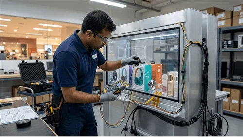
A showcase may include protective cover glass, the LCD stack, an air gap, interior glazing and a rear panel. Several near-parallel interfaces can create multiple reflected images. The brightest visible reflection may not come from the front surface.
During the mock-up, identify which surface creates each reflection by changing angle, temporarily masking a non-critical sample surface with a safe test method, or removing a non-final component where appropriate. The goal is diagnosis, not a permanent workaround.
If the project is deciding between air-spaced and bonded protective glass, see Transparent LCD Protective Glass and Lamination. That architecture changes the number and type of optical interfaces.
Define viewer zones from the real approach path
A retail display is not viewed from one laboratory point. Mark the primary customer approach path, stopping zone, close inspection position and important oblique path. For a storefront, include the outside approach and daylight or bright exterior surfaces. For an exhibition, include paths created by adjacent booths and overhead lighting.
- Primary reading zone: detailed content must remain usable.
- Approach zone: the display should attract attention and the product remain recognizable.
- Inspection zone: the shopper is close enough to judge merchandise and fine details.
- Secondary/oblique zone: not the main reading position, but important enough to avoid a severe reflection failure.
Acceptance can be stricter in the primary zone without pretending every angle must look identical.

Separate reflected light from transmitted background light
Transparent displays have a contrast challenge that opaque signage does not: the product and illuminated enclosure remain visible through the LCD. A bright product or internal background can reduce separation between dark digital regions and the scene behind the screen even when surface reflection is controlled.
Test reflected and transmitted contributions separately where possible. Observe the stack with internal product lighting at its approved state, then add store lighting sources one by one or by controlled scenes. This helps determine whether the problem is a reflected source, an overly bright background, content design or a combination.
Do not replace diagnosis with a generic brightness increase. Higher display or backlight settings can have thermal, lifetime, power and product-appearance consequences depending on the exact hardware.
Use content that exposes the weak condition
Reflection is easy to miss when a demo runs only bright saturated graphics. Include content with dark regions, fine text, neutral tones, product outlines and transitions between bright and dark scenes. Darker regions often reveal ambient reflections more clearly because reflected surroundings compete with less visible image content.
Keep representative merchandise behind the panel. A content pattern that reads well against a black test backing can fail once a bright package or polished object sits in the showcase.
The Transparent LCD Transmittance and Haze Acceptance Guide provides adjacent optical-quality context. Reflection acceptance still needs final lighting and merchandise geometry.
Fix geometry before specifying an aggressive surface treatment
If one spotlight creates a direct bright reflection into the primary zone, re-aiming or relocating it may solve more than changing the entire glass surface. A small showcase tilt can also move a reflection-if that tilt remains compatible with mounting, product presentation, touch where applicable and other optical constraints.
- Identify the source and reflecting surface.
- Test source position/aim and fixture angle.
- Control bright architectural backgrounds where feasible.
- Then compare surface treatments using the same geometry.
- Verify that a treatment does not create unacceptable haze, sparkle, color shift or cleaning problems for the selected product.
This keeps coating from becoming an expensive correction for a lighting-layout mistake.
Keep AR/AG treatment choice with the front-glass specialist page
Anti-reflective and anti-glare approaches can change the visual result in different ways, and the exact construction matters. Detailed treatment choice belongs to the sibling anti-reflection front-glass guide. For installed reflection control, compare candidate surfaces in the same full-size geometry with the same content, product, lighting, viewing zones and cleaning state.
Do not borrow a reflectance or haze number from a different glass stack and treat it as the showcase result. If a numerical optical requirement is used, tie it to a defined measurement method and exact configuration.
Use measurements to support, not replace, field viewing
Electronic-display test methods such as ISO 9241-307:2008 provide useful context for repeatable display measurements. A transparent retail showcase adds merchandise, multiple glazing interfaces and site lighting, so a single panel measurement cannot describe the whole installed experience.
Useful evidence can include luminance or illuminance measurements tied to geometry, photographs with controlled camera settings, source/viewer drawings and visual ratings by defined reviewers. When comparing photographs, control exposure and white balance; automatic smartphone exposure can make different reflection conditions look artificially similar.
Build a lighting-scene acceptance set
| Scene | What changes | What to inspect |
|---|---|---|
| Normal trading | Approved ceiling/accent and internal lighting | Primary-zone readability and product visibility |
| Bright storefront/daylight | Exterior or window contribution is high | Window/sky/architectural reflections and dark-content washout |
| Accent-light focus | Spotlights are aimed at merchandise | Specular reflections and duplicate bright images |
| Close inspection | Viewer moves near glass | Local reflections, surface haze and fine product detail |
| Post-cleaning | Approved cleaned surface condition | Streaks, treatment appearance and reflection consistency |
Use only scenes relevant to the installation. Do not add daylight testing to an interior location with no daylight exposure because it appears in a generic checklist.

Approve geometry with representative merchandise installed
Products can be bright, glossy, metallic, black, white or mirror-like. They also move during merchandising. Include difficult representative products and normal shelf positions in the final review. Record the product/background condition alongside lighting and content so a later complaint can be reproduced.
View the showcase after normal cleaning because fingerprints, streaks and residue can add scattering or reflection absent from the pristine engineering sample.
Retest changes that move a source, surface or viewer relationship
Revalidation should follow changes to luminaire position/aim, showcase angle, front glass/treatment, protective glass, panel/optical stack, internal product lighting, store layout, bright nearby signage, content style, merchandise category or cleaning process when those changes affect the approved condition.
A component substitution with the same nominal size can still change reflection or haze. Record the exact glass/panel revision and compare it against the same installed scenes.
For broader commissioning, the Transparent LCD Installation Acceptance Checklist can carry approved lighting scenes and viewer zones into site sign-off.
Use a source-to-viewer troubleshooting sequence
- Locate the dominant reflected source from the affected viewer zone.
- Identify the surface producing the reflection.
- Check whether lighting aim or showcase geometry can remove it from the critical zone.
- Separate reflection from excessive transmitted/background brightness.
- Retest with representative dark/bright content and merchandise.
- Only then compare front-glass treatment options on unchanged geometry.
- Approve the complete lighting scene and record change triggers.
This sequence preserves a clear boundary with coating procurement and makes field troubleshooting faster.
Transparent LCD reflection control is primarily an installed-geometry problem. Map sources, surfaces and viewer zones, separate reflection from background light, expose the weakness with representative content, and compare coatings only after lighting geometry is understood.
For product and solution context, see Transparent LCD Screen and Transparent Display Case.