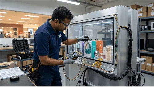
Protective glass on a transparent LCD does more than shield the panel. It adds mass, optical interfaces, edge details, thermal constraints, cleaning surfaces and a replacement decision. Bonding the glass can improve one part of the stack while making field repair harder; leaving an air gap can simplify replacement while adding surfaces that reflect light or collect contamination.
The right construction depends on what the showcase must survive and how it will be serviced. Specify the hazard first, then choose the glass, support method, gap or lamination architecture, edge treatment and replacement strategy as one system. Do not approve the stack from a glass datasheet alone.
Define what the cover is protecting against
"Protective glass" is too broad to be an engineering requirement. A locked museum-style case, an unattended public retail display and a staffed counter can face different contact conditions. Define foreseeable contact, cleaning frequency, access control, fixture movement and the consequence of breakage.
Distinguish the transparent LCD panel from the outer cover. The cover may be sacrificial and replaceable, structural within the fixture, part of a laminated assembly, or simply an optical barrier. Each role changes support and service decisions.
Do not infer a universal thickness or impact rating from the product family. Safety-glazing and structural requirements depend on construction and market. Use applicable local rules, glass-supplier documentation, fixture engineering and project risk assessment.
Choose an air gap or bonded stack for the whole lifecycle
The decision between an air-spaced cover and an adhesive-bonded construction must include optics, mechanics, manufacturing, cleaning, rework and field service.
| Consideration | Air-spaced cover | Bonded or laminated cover |
|---|---|---|
| Field replacement | Can allow the cover to be replaced separately if the frame is designed for it | May require replacing or reworking a larger optical assembly |
| Optical interfaces | Additional air/glass interfaces can create visible reflections | Bonding changes interface behavior; exact result depends on materials and process |
| Contamination risk | Internal surfaces need sealing and cleaning strategy | Bond-line quality, bubbles, edge condition and compatibility become process controls |
| Mechanical coupling | Cover and panel can have more independent movement | Stress can transfer through the bonded stack depending on materials and support |
| Rework | Often simpler when seals and fasteners are serviceable | Can require specialized separation, cleaning and rebonding or assembly replacement |
Neither architecture is automatically better. Approve the one whose production process and service plan can be controlled for the intended showcase.

Count every optical interface in the installed stack
A transparent display is judged while the viewer looks at digital content and through the display toward merchandise. Every added surface can influence reflections, haze, ghost images, color and product visibility. Evaluate the complete stack: front cover, gap or adhesive, panel surfaces, internal glazing and other showcase glass.
ISO 9241-307:2008 provides useful test-method context for electronic visual displays, but it does not supply one universal transparent-showcase limit for protective-glass loss or reflection. Set project acceptance on the actual installed stack.
For optical clarity measurement language, use the separate Transparent LCD Transmittance and Haze Acceptance Guide. This page keeps ownership of protective-stack architecture and service consequences.
Keep front-surface coating selection in its own decision
Protective-glass specifications often expand until they duplicate coating selection. Separate them. This article asks whether the cover architecture provides mechanical protection, acceptable optical behavior, support and serviceability. The newer Transparent LCD Anti-Reflection Front Glass guide owns coating choice, reflectance, haze and cleaning trade-offs.
If a coating is part of the selected cover, include it in the final sample and replacement specification. Do not use "AR" or "AG" as proof that the complete glass/panel/showcase stack will look acceptable under site lighting.
Design the edge before testing the center
Glass durability and serviceability depend heavily on edges, holes, cutouts, support points and contact with the frame. Define edge finish, corner treatment, clearance to hard parts, gasket/support condition, fastener relationship and how assembly tolerance is absorbed.
A cover that survives a demonstration at the center can still be vulnerable if an edge is damaged during installation or clamped against a rigid metal feature. Protect edges during shipping and assembly, inspect before installation, and make sure service does not require prying against exposed glass.
If the fixture uses removable glass, provide a handling method and safe support location for the removed panel.

Allow for frame movement and temperature gradients
Glass, metal frames, adhesives, gaskets and the LCD assembly do not necessarily expand together. Temperature gradients from backlighting, sunlight, chilled merchandise or HVAC can change clearances and stress. The design must tolerate the specified project environment without turning the cover into a rigid clamp on the display.
Do not copy an expansion allowance from another fixture. Use actual materials, dimensions, support philosophy, supplier data and the installation temperature envelope. The Transparent LCD Thermal Expansion and Glass Stress guide owns the detailed frame-clearance and stress-control problem.
Treat lamination quality as a manufacturing process
If the cover is bonded, document the approved adhesive or lamination material, surface preparation, cleanliness requirements, process conditions supplied by the material/process owner, edge condition, allowable cosmetic defects and inspection method. The final optical sample should use the same stack and process intended for production.
Inspect the bonded area in transmitted and reflected viewing conditions. Look for bubbles, contamination, local distortion, edge lift, uneven optical appearance and defects that become visible against real merchandise or representative dark/bright content. Define which defects are cosmetic, which interfere with viewing and which can threaten durability.
A perfect small coupon is not enough if the full-size panel uses different pressure, support, cleaning or edge conditions.
Decide the repair philosophy before approving the bond
A bonded cover changes the spare-parts model. Determine whether field service replaces only the cover, the complete bonded panel assembly or a larger display module. If separation and rebonding require controlled equipment, clean conditions or specialist skill, do not describe that as ordinary store-level repair.
- Define the service role allowed to perform the replacement.
- Identify the spare part and approved substitutions.
- State what alignment or optical condition must be restored.
- Identify single-use adhesive, gasket or seal parts.
- Control contamination during the task.
- Define visual and functional tests that close the repair.
Routine electronics service should avoid this optical repair path. See Transparent LCD Service Access Design for that boundary.
Build an optically and mechanically representative sample
Acceptance should use a production-size or demonstrably representative stack with the actual panel, protective glass, gap/adhesive, frame, gaskets, specified coatings, internal lighting and viewing geometry. Show representative merchandise behind the display and run content states sensitive to reflection and haze.
- Bright graphics over dark merchandise.
- Dark graphics over bright merchandise.
- Fine text or product detail viewed through the transparent area.
- Normal lighting and the most reflective approved lighting condition.
- Primary shopper position plus important oblique views.
- Freshly cleaned glass using the approved routine cleaning method.
Photographs are useful records, but automatic exposure can hide or exaggerate reflections. Combine them with controlled visual inspection and measurements appropriate to the requirement.

Revalidate substitutions that change the interfaces
Retest when cover-glass supplier, thickness, edge treatment, coating, adhesive, gap, gasket, frame support, panel or cleaning process changes in a way that can affect the approved result. A substitute can match nominal dimensions while changing color, reflection, haze, stress, service method or durability.
Keep the approved construction drawing, material/process references, measurement or sample record and replacement instructions together. That evidence is more useful than a generic note that the unit has "tempered glass" or "laminated glass."
Three questions settle the architecture
- What hazard must the cover resist? This defines the mechanical and safety evidence.
- What optical change can the project tolerate? This defines the complete-stack test, not just the glass datasheet.
- What will field service replace after damage? This defines whether the gap, bond line, frame and spare-parts plan are practical.
When all three answers are explicit, protective glass becomes a controlled part of the transparent display instead of a late accessory.
Use Transparent LCD Screen for product-family context and Transparent Display Case for solution context. Mechanical protection, optical quality and serviceability should be approved together on the exact stack that will be built.