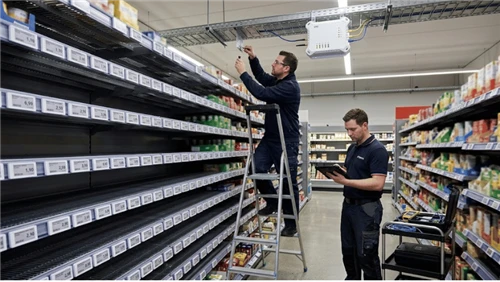
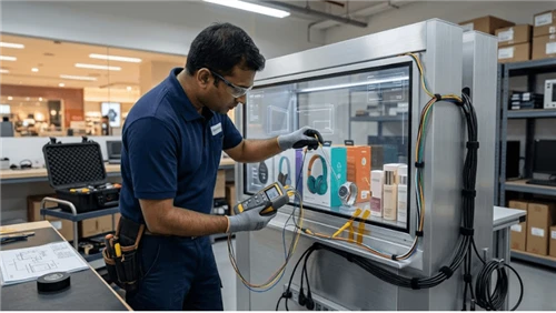
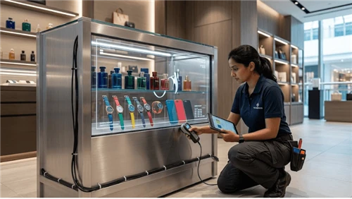
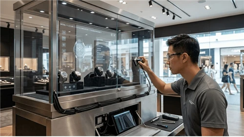
An LCD can leave the factory visually clean and develop corner light leakage, temporary pressure marks, touch distortion, or glass stress only after its chassis is pulled onto an uneven welded frame. That is the practical reason to treat commercial LCD mounting flatness bezel stress as a system problem rather than a specification-line feature. This guide is for Display enclosure engineers, OEM integrators, fixture designers, manufacturing teams, and buyers and answers one narrow question: How do you mount a commercial LCD into a custom enclosure or shelf fixture without twisting the panel, overcompressing the bezel, or creating pressure-related image defects? The focus is mechanical datum/flatness + clamp forces + optical symptoms.
The evidence chain should follow the product from specification to field use. Begin with model-specific documentation, connect it to drawings and configuration for the finished display/fixture assembly, then check the difficult interactions on production-equivalent hardware. Archive the exact revision and the condition under which it passed. After rollout, compare incidents with that baseline so old evidence is not reused after a substitution. The important interfaces include panel mechanics, video source, display settings, optical condition, mounting, and service replacement. When a numerical limit matters, source it from the applicable standard, the exact model, or an approved project requirement instead of turning a convenient example into a universal specification.

Keep the scope connected to Bar-Shaped LCD Screen, Bar LCD CMS Integration, Bar LCD Thermal Management. They establish adjacent product and integration context; this article keeps its own keyword owner and engineering boundary.
The topic-lock research reviewed public category/technical material from Samsung Business Displays, LG Commercial Display, and Sharp/NEC Display Solutions. The purpose was to identify common buyer language and gaps in implementation detail. Competitor claims are not used as LEGOYO facts, and competing commercial pages are not linked from the final article.
Set the boundary before selecting a fix
Bar-LCD alignment pages own multi-unit positioning; this page owns panel flatness, local clamp load, chassis twist, bezel contact, and optical symptoms caused by mechanical stress. The controlling object is the finished display/fixture assembly, not a loose component on a laboratory table. The engineering group should describe the supported condition around reference datum and enclosure flatness, mount-point coplanarity, and fastener sequence and controlled clamp load; name the owner of each interface; and state what the user or technician sees when it falls outside the approved state. That approach separates a real component defect from a fixture, configuration, content, environment, or service problem.
Write exclusions next to the scope. This article focuses on mechanical datum/flatness + clamp forces + optical symptoms and should not absorb every adjacent topic merely because the same hardware is involved. The first adverse case to place in the plan is "A warped welded frame pulls the display chassis out of plane." If the project cannot explain how that condition is detected, contained, and retested, the boundary is still too vague for procurement or acceptance.
Scope-to-evidence map
| Control point | Review action | Adjacent dependency | Output |
|---|---|---|---|
| reference datum and enclosure flatness | reproduce a service state | Interaction with fastener sequence and controlled clamp load | commissioning evidence tied to production revision |
| mount-point coplanarity | confirm recovery after disturbance | Interaction with bezel/gasket contact pressure | commissioning evidence tied to production revision |
| fastener sequence and controlled clamp load | establish the reference condition | Interaction with allowance for chassis and panel tolerance stack | commissioning evidence tied to production revision |
| bezel/gasket contact pressure | expose the dependency | Interaction with cable or bracket forces applied near the panel | commissioning evidence tied to production revision |
| allowance for chassis and panel tolerance stack | make the state observable | Interaction with thermal expansion clearance | commissioning evidence tied to production revision |
| cable or bracket forces applied near the panel | challenge a tolerance edge | Interaction with inspection for stress-related optical change after assembly | commissioning evidence tied to production revision |
Engineering controls to specify explicitly
The controls below come directly from the failure boundary for commercial LCD mounting flatness bezel stress. They are intentionally more specific than generic product features. For each one, define the reference state, the interaction that can change it, the production/service check, and the change that invalidates the old result.
Reference datum and enclosure flatness
For reference datum and enclosure flatness, the key issue is whether the final assembly keeps the intended state after tolerance, service and environment are added. Describe the variable that controls it, which part or configuration establishes the reference, and how a technician can inspect it without relying on tribal knowledge. Pair the check with mount-point coplanarity, because those two conditions can move together after a field modification. The negative case "A warped welded frame pulls the display chassis out of plane" is useful because it forces the review away from nominal geometry or default settings. The expected outcome should say what remains functional, what becomes unavailable, and what evidence distinguishes this condition from an unrelated failure.
Mount-point coplanarity
Put mount-point coplanarity into the requirement set before tooling and quotations are frozen. Set the variable that controls it, which part or configuration establishes the reference, and how a technician can confirm it without relying on tribal knowledge. Pair the check with fastener sequence and controlled clamp load, because those two conditions can move together after a revision. The negative case "Fasteners are tightened sequentially from one corner and preload the panel unevenly" is useful because it forces the review away from nominal geometry or default settings. The expected outcome should say what remains functional, what becomes unavailable, and what evidence distinguishes this condition from an unrelated latent defect.
Fastener sequence and controlled clamp load
Fastener sequence and controlled clamp load is an installation condition, not a drawing label. Bound the variable that controls it, which part or configuration establishes the reference, and how a technician can validate it without relying on tribal knowledge. Pair the check with bezel/gasket contact pressure, because those two conditions can move together after a service intervention. The negative case "A cosmetic bezel presses directly on the active display area" is useful because it forces the review away from nominal geometry or default settings. The expected outcome should say what remains functional, what becomes unavailable, and what evidence distinguishes this condition from an unrelated configuration fault.
Bezel/gasket contact pressure
The design review for bezel/gasket contact pressure needs a reference that survives production and field service. Document the variable that controls it, which part or configuration establishes the reference, and how a technician can verify it without relying on tribal knowledge. Pair the check with allowance for chassis and panel tolerance stack, because those two conditions can move together after a replacement. The negative case "A cable bundle pushes the rear cover and changes panel flatness" is useful because it forces the review away from nominal geometry or default settings. The expected outcome should say what remains functional, what becomes unavailable, and what evidence distinguishes this condition from an unrelated drift.
Allowance for chassis and panel tolerance stack
For allowance for chassis and panel tolerance stack, the key issue is whether the final assembly keeps the intended state after tolerance, service and environment are added. Frame the variable that controls it, which part or configuration establishes the reference, and how a technician can prove it without relying on tribal knowledge. Pair the check with cable or bracket forces applied near the panel, because those two conditions can move together after a change. The negative case "Thermal expansion closes a nominal gap and creates pressure after warm-up" is useful because it forces the review away from nominal geometry or default settings. The expected outcome should say what remains functional, what becomes unavailable, and what evidence distinguishes this condition from an unrelated integration error.
Cable or bracket forces applied near the panel
Put cable or bracket forces applied near the panel into the requirement set before tooling and quotations are frozen. Pin down the variable that controls it, which part or configuration establishes the reference, and how a technician can exercise it without relying on tribal knowledge. Pair the check with thermal expansion clearance, because those two conditions can move together after a configuration edit. The negative case "A touch overlay shows localized false touches where the stack is compressed" is useful because it forces the review away from nominal geometry or default settings. The expected outcome should say what remains functional, what becomes unavailable, and what evidence distinguishes this condition from an unrelated edge-case breakdown.

Thermal expansion clearance
Thermal expansion clearance is an installation condition, not a drawing label. Establish the variable that controls it, which part or configuration establishes the reference, and how a technician can demonstrate it without relying on tribal knowledge. Pair the check with inspection for stress-related optical change after assembly, because those two conditions can move together after a site alteration. The negative case "A warped welded frame pulls the display chassis out of plane" is useful because it forces the review away from nominal geometry or default settings. The expected outcome should say what remains functional, what becomes unavailable, and what evidence distinguishes this condition from an unrelated mismatch.
Inspection for stress-related optical change after assembly
The design review for inspection for stress-related optical change after assembly needs a reference that survives production and field service. Define the variable that controls it, which part or configuration establishes the reference, and how a technician can check it without relying on tribal knowledge. Pair the check with reference datum and enclosure flatness, because those two conditions can move together after a substitution. The negative case "Fasteners are tightened sequentially from one corner and preload the panel unevenly" is useful because it forces the review away from nominal geometry or default settings. The expected outcome should say what remains functional, what becomes unavailable, and what evidence distinguishes this condition from an unrelated service escape.
Trace the interfaces that can move the result
Commercial lcd mounting flatness bezel stress sits inside the finished display/fixture assembly and can be changed indirectly by panel mechanics, video source, display settings, optical condition, mounting, and service replacement. Build the interface map before troubleshooting. That prevents the first visible symptom from becoming the assumed root cause and gives service teams a sequence for checking recent changes before parts are swapped.
| Interface layer | Variables to connect | Practical challenge | Traceability |
|---|---|---|---|
| Mechanical/fixture | reference datum and enclosure flatness; bezel/gasket contact pressure | Repeat the task with service access, cleaning, replenishment or replacement steps included | log unit/revision and result |
| Electrical or device state | mount-point coplanarity; allowance for chassis and panel tolerance stack | Compare a substitute part or revision with the approved evidence before release | log unit/revision and result |
| Configuration/software | fastener sequence and controlled clamp load; cable or bracket forces applied near the panel | Hold the approved baseline and move one physical variable at a time | log unit/revision and result |
| Environment/content | bezel/gasket contact pressure; thermal expansion clearance | Observe power/device state while the linked mechanical or optical condition is changed | log unit/revision and result |
| Service/operations | allowance for chassis and panel tolerance stack; inspection for stress-related optical change after assembly | Read back the configured state before and after restart, reset or replacement | log unit/revision and result |
| Supplier/lifecycle | cable or bracket forces applied near the panel; reference datum and enclosure flatness | Exercise representative and difficult site conditions rather than laboratory defaults | log unit/revision and result |
The map should be useful during a real incident. A technician should be able to answer: what changed last, which of reference datum and enclosure flatness or mount-point coplanarity could explain the symptom, and what quick observation preserves evidence before recovery is attempted? If the answer requires unwritten knowledge from the original designer, the handover is incomplete.
Failure modes worth provoking on purpose
Normal-operation testing is necessary but not sufficient. The expensive incidents usually sit at boundaries: partial faults, service reassembly, configuration drift, or conditions that recover temporarily. For commercial LCD mounting flatness bezel stress, the following cases are high-value because they exercise the actual integration boundary rather than an isolated feature.
| Failure condition | Controlled investigation | Likely checkpoints | Evidence / closure |
|---|---|---|---|
| A warped welded frame pulls the display chassis out of plane | compare a known-good unit or reference condition | Check reference datum and enclosure flatness and fastener sequence and controlled clamp load | test record; corrective action; targeted retest |
| Fasteners are tightened sequentially from one corner and preload the panel unevenly | verify the following transaction/content cycle, not just the immediate reset | Check mount-point coplanarity and bezel/gasket contact pressure | test record; corrective action; targeted retest |
| A cosmetic bezel presses directly on the active display area | reproduce it on a production-equivalent assembly | Check fastener sequence and controlled clamp load and allowance for chassis and panel tolerance stack | test record; corrective action; targeted retest |
| A cable bundle pushes the rear cover and changes panel flatness | change only the suspected variable while holding the baseline | Check bezel/gasket contact pressure and cable or bracket forces applied near the panel | test record; corrective action; targeted retest |
| Thermal expansion closes a nominal gap and creates pressure after warm-up | capture the system state before applying the recovery action | Check allowance for chassis and panel tolerance stack and thermal expansion clearance | test record; corrective action; targeted retest |
| A touch overlay shows localized false touches where the stack is compressed | repeat after the normal service or reset procedure | Check cable or bracket forces applied near the panel and inspection for stress-related optical change after assembly | test record; corrective action; targeted retest |
Keep symptom, cause and consequence separate
When "A warped welded frame pulls the display chassis out of plane" occurs, record the user-visible symptom first, then the device/configuration state, recent site alteration, diagnostic finding, and final correction. Do the same for "Fasteners are tightened sequentially from one corner and preload the panel unevenly." This makes incidents comparable across sites. A reboot, reseat or adjustment can be an approved recovery step, but it should not erase the clues needed to determine whether the same mismatch is recurring.
Turn the risk into an acceptance plan
Use a small number of well-defined tests that expose important interfaces rather than a long checklist of cosmetic observations. Each test should have a reason, an owner and a retest trigger. Exact numerical limits remain tied to model documentation, standards or buyer-approved requirements; the table below describes method and evidence rather than inventing a universal number.
| Test ID | Primary focus | Method | Adverse condition | Evidence |
|---|---|---|---|---|
| A10-1 | reference datum and enclosure flatness | Baseline reference datum and enclosure flatness; then challenge fastener sequence and controlled clamp load | Include adverse case: A warped welded frame pulls the display chassis out of plane | capture setup, observation, disposition and retest |
| A10-2 | mount-point coplanarity | Baseline mount-point coplanarity; then challenge bezel/gasket contact pressure | Include adverse case: Fasteners are tightened sequentially from one corner and preload the panel unevenly | capture setup, observation, disposition and retest |
| A10-3 | fastener sequence and controlled clamp load | Baseline fastener sequence and controlled clamp load; then challenge allowance for chassis and panel tolerance stack | Include adverse case: A cosmetic bezel presses directly on the active display area | capture setup, observation, disposition and retest |
| A10-4 | bezel/gasket contact pressure | Baseline bezel/gasket contact pressure; then challenge cable or bracket forces applied near the panel | Include adverse case: A cable bundle pushes the rear cover and changes panel flatness | capture setup, observation, disposition and retest |
| A10-5 | allowance for chassis and panel tolerance stack | Baseline allowance for chassis and panel tolerance stack; then challenge thermal expansion clearance | Include adverse case: Thermal expansion closes a nominal gap and creates pressure after warm-up | capture setup, observation, disposition and retest |
| A10-6 | cable or bracket forces applied near the panel | Baseline cable or bracket forces applied near the panel; then challenge inspection for stress-related optical change after assembly | Include adverse case: A touch overlay shows localized false touches where the stack is compressed | capture setup, observation, disposition and retest |
What the evidence package should contain
- Production model/revision and the parts that establish reference datum and enclosure flatness
- Fixture, enclosure, content or configuration needed to reproduce mount-point coplanarity
- Method and tool used to inspect or measure fastener sequence and controlled clamp load, including tool status where relevant
- Expected behavior for the difficult case "A warped welded frame pulls the display chassis out of plane" and the observed behavior
- Defect disposition and corrective action if bezel/gasket contact pressure does not meet the project boundary
- Explicit retest triggers covering allowance for chassis and panel tolerance stack, supplier substitution and field service
A useful commissioning evidence lets a reviewer reconstruct why the unit passed months later. Photographs without configuration context, measurements without the test condition, or logs without unit identity are easy to collect and difficult to use. Store the evidence with the requirement and defect disposition rather than in an unrelated project folder.
RFQ questions that reveal hidden scope
Ask for evidence and responsibility together. A supported feature with an unowned interface still becomes project risk. For commercial LCD mounting flatness bezel stress, require answers that name the exact model/revision, included elements, exclusions, and service method. The questions below are intended to reveal whether two quotations describe the same responsibility boundary.
- What mounting datum and flatness requirement applies to the exact display chassis?
- Which holes or brackets are structural mounting points versus alignment features?
- What fastener sequence or load-control method is recommended?
- Where must bezels, gaskets, or cover glass avoid direct pressure?
- What thermal-growth clearance should the enclosure preserve?
- Which post-install visual and touch checks detect mechanical stress before shipment?
Before comparing price, normalize these five items
- Identify the exact quoted revision and every part/configuration that affects reference datum and enclosure flatness
- Ask for reviewable evidence around mount-point coplanarity and the exclusions around fastener sequence and controlled clamp load
- Name who owns integration and field verification of bezel/gasket contact pressure
- Record the service/replacement method that can change allowance for chassis and panel tolerance stack
- Treat any workaround affecting cable or bracket forces applied near the panel as a documented deviation with owner and retest
A different architecture is not automatically worse. If a supplier handles reference datum and enclosure flatness another way, check whether the method still serves the use case, can be validate on delivered hardware, and can be maintained after replacement. Keep the outcome and evidence requirement fixed; avoid mandating an implementation unless the project genuinely depends on it.
Keep the approved state alive after handover
A passed unit can drift after store remodeling, cleaning, replacement parts or software maintenance. For commercial LCD mounting flatness bezel stress, give operations the baseline configuration, diagnostic or inspection cues, safe recovery method, replacement constraints, and retest triggers. This is especially important when the immediate service action can make the symptom disappear without proving its cause.
Metrics that can reveal drift
- mounting-related optical rework
- corner light-leak complaints after installation
- panel/frame flatness deviations
- touch faults linked to enclosure pressure
- rework after fixture supplier changes
Trend these signals by site, production revision, service action and time. For example, repeated movement in "mounting-related optical rework" after a particular replacement or configuration release is stronger evidence than isolated anecdotes. The goal is to connect field behavior back to reference datum and enclosure flatness, mount-point coplanarity, or another controlled variable while the evidence is still recoverable.
Write retest triggers into the service package
- A hardware or material change can alter reference datum and enclosure flatness or mount-point coplanarity
- Software, driver or configuration changes can alter fastener sequence and controlled clamp load where it participates in the result
- Fixture, mounting, lighting, cleaning, cable, power or site changes can move bezel/gasket contact pressure
- A replacement part or supplier lot changes the baseline for allowance for chassis and panel tolerance stack
- A repeat of "A warped welded frame pulls the display chassis out of plane" challenges an assumption used during the original approval
- Relocation or reassembly disturbs cable or bracket forces applied near the panel or another physical datum
For neighboring decisions, use Shelf-Edge LCD Content Design, LCD Image Retention Prevention, Commercial Display vs Consumer TV, LEGOYO Products, Supermarket Solutions. Those pages should remain separate owners for their broader subjects; use them to understand dependencies rather than copying their acceptance result into this one.

Final decision gate: approve, revise, or stop
- Boundary: can another team reproduce the configuration and exclusions around reference datum and enclosure flatness?
- Interface: is ownership clear where mount-point coplanarity interacts with fastener sequence and controlled clamp load?
- Acceptance: did the evidence include the adverse condition "A warped welded frame pulls the display chassis out of plane"?
- Recovery: can "Fasteners are tightened sequentially from one corner and preload the panel unevenly" be contained without erasing diagnostic context?
- Lifecycle: will a future site alteration affecting bezel/gasket contact pressure trigger a comparison with the baseline?
Close commercial LCD mounting flatness bezel stress as approve, revise, or stop rather than "looks fine." If an unresolved item must move into pilot operation, state the temporary control, evidence owner, and the exact event that closes the gap. That keeps a pilot assumption from quietly becoming the fleet standard.
FAQ
Q: What is the first thing to verify when a warped welded frame pulls the display chassis out of plane?
A: Confirm the approved baseline for reference datum and enclosure flatness and mount-point coplanarity before changing parts or settings. Capture the state and recent service/configuration changes, then reproduce the symptom if it is safe to do so.
Q: How should reference datum and enclosure flatness be documented?
A: Use a model/revision-specific datum, drawing, configuration readback, inspection method or test record. The document should tell production and service how to recognize the approved state and when a retest is required.
Q: Can supplier documentation replace project testing for commercial LCD mounting flatness bezel stress?
A: No. Supplier documentation defines product capability and limits. Project testing verifies the chosen fixture, software, environment, content, workflow and service method in the final integrated configuration.
Q: How can a team distinguish "Fasteners are tightened sequentially from one corner and preload the panel unevenly" from another fault?
A: Compare the symptom with the controlled variables most likely to affect it-especially fastener sequence and controlled clamp load and bezel/gasket contact pressure. Change one suspected variable at a time and keep logs, measurements or photos tied to the exact unit.
Q: What changes should force a retest of allowance for chassis and panel tolerance stack?
A: Retest after substitutions or service changes that can alter the same load path, optical path, electrical state, configuration or environment. A recurring field incident is also a valid trigger even when no planned engineering change is known.
Q: How should two supplier solutions be compared?
A: Normalize exact configuration, included accessories, evidence, integration responsibility, deviations, service access and replacement strategy. Initial price is not comparable until those boundaries are aligned.
Final recommendation
The final deliverable should make design intent visible to procurement, factory, commissioning and service teams alike. For commercial LCD mounting flatness bezel stress, keep reference datum and enclosure flatness, mount-point coplanarity, and fastener sequence and controlled clamp load inside the same evidence chain. Test at least one difficult condition, preserve the result, and make future site alteration trigger an explicit comparison rather than an assumption.
For broader context, return to LEGOYO products and the technical blog. When a project is ready for configuration review, prepare site conditions, interfaces, intended workflow and acceptance evidence before using Request a Quote.