LCD faults are easier to diagnose when the first question is "what exactly is the screen doing?" rather than "which part should we replace?" Flicker, lines, no signal, black screen, wrong colors, and intermittent dropouts can originate in different layers: AC/DC power, the media source, cable and connector, video negotiation/timing, display controller, backlight, panel, thermal conditions, or the application itself.
A useful field process starts with the symptom, preserves evidence, changes one variable at a time, and uses known-good substitutions to separate layers. Avoid opening powered equipment or probing internal circuits unless the technician is qualified and the exact service documentation provides a safe procedure.

Capture the symptom before touching the system
Record what the user sees, when it occurs, and what changed immediately before it. A phone photo or short video can be useful for intermittent faults if it is labeled with time, display state, source, and site condition. Also record whether the display's own menu or on-screen display (OSD) is visible and stable.
The OSD is a strong discriminator. If the display's internal menu is normal while source content is missing or corrupted, the panel/backlight path may still be functioning and the investigation can move upstream toward source, cable, input, timing, or processing. If the OSD itself has the same lines or instability, the fault is more likely inside the display path or power/thermal environment.
Do not treat this as proof of a single component. It is an isolation clue that reduces unnecessary substitutions.

Start with safe external checks
- Confirm the display is receiving the expected external power and that any accessible power indicator matches the normal state.
- Check that the intended input is selected and the source device is running.
- Inspect the video cable for full seating, damage, sharp bends, adapter problems, or obvious strain.
- Check whether the fault changes with a controlled source restart or display restart allowed by the operating procedure.
- Compare the display OSD/menu with the source image.
For installations where cable movement or mount position affects the symptom, the Commercial LCD Connector Retention guide explains strain relief, service loops, and port loading in more detail.
Completely dark screen: separate power, backlight, and video state
First determine whether the display is truly unpowered or simply showing black content. Look for normal indicators, audible device behavior where relevant, backlight glow, OSD response, and remote management state if available. A source can output a black frame while the display is healthy; a display can also have logic power while the backlight is unavailable.
Use a known-good source and cable only after confirming the safe external power state. If the display has no external sign of operation after approved power checks, escalate according to the equipment service procedure instead of guessing at internal voltages.
Backlight on but no picture: isolate source and input path
If the screen is illuminated and the OSD appears, check the selected input, source output, cable/adapter chain, and supported timing. Connect the source to a known-good display where practical, or connect a known-good source to the suspect display. This A/B method changes one side of the link while preserving the other.
If direct connection works but the installed path fails, reintroduce extenders, converters, wall plates, switches, or adapters one at a time. The point is to find the first layer where a known-good signal stops being useful.
No signal and intermittent dropouts: look for events that break the link
An intermittent no-signal condition often correlates with a physical or state transition: cable movement, a player reboot, hot-plug detection, an extender power cycle, input switching, a display wake event, or a thermal change. Build a timeline around the dropout.
Inspect connectors and retention before replacing the panel. Then simplify the path. Use the shortest practical known-good direct connection for isolation, while keeping the production timing. If the direct path is stable, add each intermediate component back.
If the system intentionally uses multiple sources or automatic switching, consult the Commercial LCD Input Signal Failover guide. Failover architecture and source-priority policy are different tasks from diagnosing an unexplained no-signal fault.
Visible flicker: decide whether the image, backlight, or signal is changing
Describe the flicker. Does the entire screen flash black? Does brightness pulse while the image remains synchronized? Does only one content region change? Does the fault appear after warm-up or at a particular brightness setting? Does it react to cable movement?
Whole-screen black flashes suggest a signal, input, power, or restart event more than a localized panel defect. Brightness modulation without signal loss can point toward backlight control or power. A content/application animation can also be mistaken for display flicker, so compare the OSD or a static test image.
Camera-visible banding is a separate problem. A display can look stable to the human eye while a rolling-shutter camera records dark bands because of backlight modulation. Use the Commercial LCD PWM Dimming and Camera Flicker guide when the fault exists mainly in photos or video.
Vertical or horizontal lines: determine whether they belong to content or panel output
Use several independent images: the display OSD/menu, a static test pattern from a known-good source, and the normal application. A line that appears in the same physical pixel position over every source and the OSD is different from a line embedded in one video file or generated by one source.
For intermittent lines, note whether they change with warm-up, enclosure pressure, cable movement, or input changes. Do not press on the panel or flex the enclosure as a casual diagnostic method; mechanical pressure can create new damage. If a fixed line persists across the OSD and known-good sources, retain a clear photograph and escalate with the display model/revision and service evidence.
Wrong colors, noise, or unstable geometry: test timing and data path
Color shifts, sparkling pixels, intermittent blocks, shifted images, or unstable synchronization can point toward a marginal signal path, incorrect timing/configuration, mapping problem, source output issue, or internal controller/panel path. Start by returning to the approved native production mode and simplifying the video path.
For raw or semi-integrated LCDs, verify the exact panel mapping, timing, connector, and controller configuration. For finished commercial displays, verify the source output mode, interface, cable/adapter chain, and any scaler or extender. The LCD Interface Selection guide provides interface-design context, but troubleshooting should focus on the approved configuration rather than redesigning the system mid-incident.
Faults after warm-up: make time and temperature part of the test
A display that works cold and fails later should be observed against elapsed operating time, brightness state, content load, enclosure temperature, ventilation state, and nearby heat sources. Do not use touch alone as a temperature measurement.
Reproduce the failure in the production-equivalent enclosure and log the conditions that change when the fault begins. If opening a cabinet makes the fault disappear, that is evidence of an environmental/thermal interaction, not proof that a specific internal component is defective. Compare against the exact product operating limits and approved installation conditions.
Reboots and blanking: check power and system restart evidence
If the display repeatedly restarts, record whether the source, display, or both restart together. Check external power connections, power supplies, shared branch behavior, scheduled power control, and any load event that coincides with the reset. A reboot that occurs when another peripheral starts can be a system power problem rather than an LCD defect.
Use logs from players, controllers, power-management systems, or remote monitoring when available. Correlating timestamps is more useful than repeatedly power-cycling the equipment until the fault temporarily disappears.
Use a known-good field kit to avoid guesswork
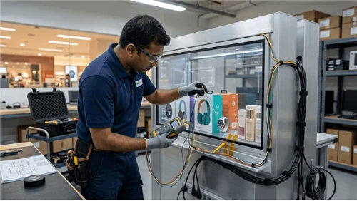
A controlled diagnostic kit can include a known-good source with approved output modes, known-good short cables for the interfaces used on site, approved adapters if unavoidable, a test image set, basic non-invasive power verification tools appropriate to the service role, cleaning materials, and configuration records. Keep the kit parts identified and periodically verify that they are still known-good.
The objective is not to carry every possible spare. It is to replace one uncertain layer with a trusted reference so the next decision is evidence-based.

Symptom-to-layer isolation table
| Observed symptom | First discriminator | Next controlled test |
|---|---|---|
| Dark / no image | Does OSD appear? | Known-good source/cable or approved power-state check |
| No signal | Does source work on another display? | Simplify signal path, then add intermediate devices back |
| Dropout with movement | Does cable/mount position correlate? | Inspect retention and test supported known-good cable |
| Visible flicker | Does OSD flicker too? | Separate source/signal event from backlight/power behavior |
| Fixed line | Is it present over OSD and all sources? | Capture evidence; isolate panel/controller path |
| Wrong color/noise | Does approved native mode restore image? | Check mapping/timing/cable/adapter chain |
| Fails warm | Is failure tied to time/temperature? | Reproduce in final enclosure and log thermal state |
Close the incident with a reproducible pass condition
After the suspected cause is corrected, rerun the condition that originally produced the fault. A cable reseat is not a completed repair until the mount movement, warm-up period, restart sequence, or input transition that triggered the incident has been repeated successfully.
Record the failed component or configuration, corrective action, final test, display/source revisions, and any follow-up monitoring. If the root cause remains uncertain but the system is returned to service, state the residual uncertainty and the evidence that should be collected if the symptom returns.
For the product-family context, see Bar LCD and Commercial LCD Displays.
Fast LCD troubleshooting comes from narrowing the layer, not from swapping parts quickly. Capture the symptom, use the OSD and known-good references to separate source from display, reproduce time/movement/thermal triggers, and finish by retesting the original failure condition.