A commercial LCD can look perfectly stable to the human eye and still produce dark bands, rolling stripes, exposure pulsing, or uneven brightness in photographs and video. The cause is often not the LCD pixel refresh itself but the way the LED backlight is dimmed. Many backlight drivers use pulse-width modulation (PWM): they switch the LEDs rapidly and change the duty cycle to control average brightness. A camera shutter or rolling-scan sensor can sample that modulation unevenly and reveal flicker that viewers do not consciously see.
This guide explains how to qualify PWM dimming when a LCD display screen category will be photographed, filmed, monitored by a vision system, or installed in a retail environment where social-media content is common. It avoids universal "safe frequency" claims because the result depends on PWM waveform, duty cycle, camera sensor, shutter, frame rate, brightness setting, and ambient lighting. The practical objective is a repeatable camera-facing acceptance test.

Distinguish Panel Refresh From Backlight Modulation
Two periodic processes can exist at the same time. The LCD panel updates image data at its own frame timing, while the backlight driver can modulate LED current at another frequency. A visible moving band can therefore remain after changing video refresh rate because the dominant interaction is between the camera exposure and the backlight, not between the camera and the video frame rate.
Start troubleshooting by separating these layers. Lock the content to a static test image, use a stable video input, and change only display brightness. If banding changes strongly with the backlight setting, the dimming method deserves investigation. If the artifact follows content motion or input timing instead, examine the player, scaling, synchronization, and signal path.
Why Brightness Setting Changes the Camera Result
With PWM dimming, brightness is typically changed by altering how long the LED is on during each cycle. At low duty cycles, a rolling shutter may capture some sensor rows while the backlight is on and others while it is off. The visible bar width, direction, and motion depend on the camera readout and exposure. This is why a display can film cleanly at one brightness setting and show severe banding at another.
Do not qualify only at maximum brightness. The deployed system may use scheduled dimming, an ambient-light sensor, night mode, or manual settings. Test the actual operating range and any automatic-control states. If the display uses content-adaptive backlight behavior, include representative bright and dark content because the driver behavior can change with scene conditions.
| Variable | Why it matters | What to record |
|---|---|---|
| Display brightness | Can change PWM duty cycle or dimming mode | OSD value and any auto-dimming state |
| Camera shutter/exposure | Controls how modulation is sampled | Shutter, exposure time, ISO/gain |
| Frame rate | Changes frame-to-frame interaction | Camera frame rate and scan mode |
| Camera sensor | Rolling/global shutter behavior differs | Exact camera or phone model |
| Ambient light | Other LED lighting can create its own flicker | Fixture state and daylight condition |
| Content | Dynamic control may respond to image level | Exact test image/video file |
Do Not Blame the Display Until Store Lighting Is Isolated
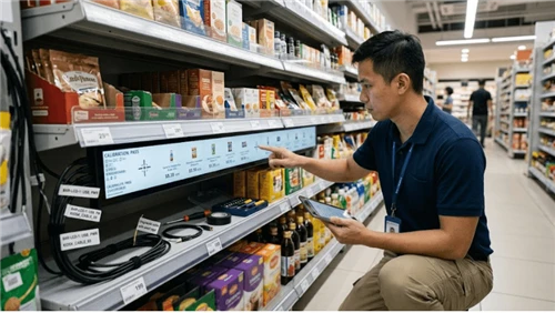
Retail ceilings, cabinet lights, shelf lighting, and decorative LED strips can also use PWM or low-frequency driver modulation. A camera pointed at the display sees the combined scene. Before changing the LCD, repeat the test with surrounding luminaires controlled or temporarily disabled where safe. If the banding remains inside the display area while surrounding surfaces are stable, the display backlight becomes a stronger suspect.
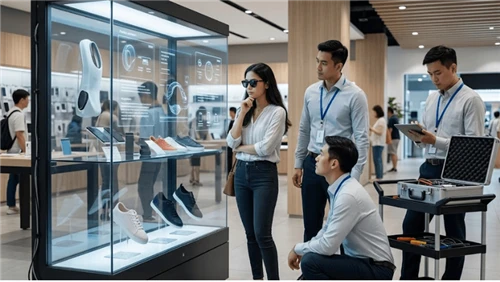
Transparent showcases and illuminated shelving need extra care because interior lighting can be visible through or reflected by the display. The camera may capture two different modulation systems at once. Each light source should be characterized independently before the full scene is approved.
Measure the Backlight Instead of Guessing From a Phone Video
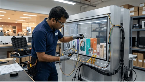
A slow-motion phone recording is a useful screening tool but not a complete measurement. Automatic exposure, frame interpolation, rolling shutter, and camera image processing can create or hide bands. For engineering validation, use a photodiode or suitable light sensor with an oscilloscope or data-acquisition instrument to observe the backlight waveform directly. Measure at the brightness settings that matter to the application.
The objective is to document modulation behavior, not to manufacture a favorable number. Record the measurement bandwidth, sensor location, brightness setting, waveform, and any mode transition. If the supplier publishes a PWM frequency, confirm whether it is fixed across the brightness range and whether there are conditions where the driver changes method.
Camera-Facing Acceptance Should Use the Real Capture Workflow
If the display will appear in product photography, livestreaming, video surveillance, remote inspection, or machine vision, qualify the exact capture devices. A display that is acceptable on one global-shutter industrial camera may fail on a consumer phone with a rolling shutter. Conversely, a phone-specific artifact may not matter to a fixed camera used by the deployed system.
Define the worst credible camera settings instead of testing every possible combination. For a retail environment, that may include the brand's common content-production camera and representative customer phones. For machine vision, use the production camera, lens, exposure, frame rate, and trigger timing.
- Lock camera auto-exposure where possible so two display samples are comparable.
- Test at planned minimum, normal, and maximum display brightness.
- Capture white, mid-gray, dark, and high-contrast content.
- Repeat with automatic dimming enabled if it is part of the field configuration.
- Test after warm-up because driver and power behavior can differ from first boot.
- Keep the original media files; compressed messaging-app copies are weak evidence.
Separate PWM Banding From Input-Signal Flicker
If the screen itself flashes, loses sync, goes black, or changes source, use the diagnosis in the commercial LCD input failover guide before concluding that PWM is responsible. PWM-related camera banding normally does not imply that the video signal is dropping. Likewise, a source-switching event can look like a brightness disturbance in a recording even when the backlight driver is stable.
Also inspect power. A backlight driver supplied from an unstable rail can show brightness modulation that is not intentional PWM. Log supply voltage during the event and compare a known-good power configuration. This is especially important in long cable runs or shared DC systems.

Specify Dimming Behavior in the RFQ
A procurement request should ask how brightness is controlled rather than simply requesting a brightness range. Ask whether the backlight driver uses PWM, DC current control, or a mixed approach; what control interface exists; whether the modulation behavior changes by brightness range; and whether the supplier can provide waveform or frequency information for the proposed configuration. If camera compatibility matters, say so explicitly.
- What dimming method is used at each operating brightness range?
- If PWM is used, is the modulation frequency fixed or mode-dependent?
- Can the supplier provide an engineering waveform or measurement method?
- Can brightness be limited to an approved camera-safe range in firmware or OSD?
- Does automatic brightness control change dimming mode?
- Can a production-representative sample be supplied for camera testing?
- Will backlight driver, LED bar, panel, or control-board substitutions trigger change notification?
- What settings must remain fixed for lot-to-lot camera-facing consistency?
Troubleshooting a Field Report of "Striped Video"
Preserve the original clip and collect the display model/revision, brightness setting, input source, camera model, camera mode, and surrounding-light state. Reproduce the scene before changing parts. Then isolate variables in this order: ambient lighting, display brightness, camera exposure, content/input stability, and backlight power. This sequence usually provides more evidence than replacing the panel first.
If the issue appears only after thermal buildup, inspect the ventilation assumptions in commercial LCD airflow and dust guide. If it appears after a power event or schedule transition, compare behavior with the commercial LCD scheduled power guide configuration. Camera artifacts often reveal a system interaction rather than a single defective component.
Turn the Design Into a Repeatable Acceptance Test
A good commercial LCD PWM dimming and camera-flicker performance decision ends with a test another engineer can repeat. The test should identify the production-representative hardware, software or firmware revision, cables and accessories, environmental condition, input data, operator action, expected result, and evidence file. Avoid a pass rule such as "works normally." A pass rule should describe what state must be observed and what exceptions are allowed.
Keep the test evidence with the same revision record used for procurement. The most useful artifact is a camera-compatibility and backlight-waveform validation sheet: one sheet that connects requirement, setup, action, observed result, defect owner, and approval. This prevents a later supplier change from being judged against a memory of the pilot rather than the approved baseline.
- Freeze the test configuration and record model/revision identifiers.
- Create normal, boundary, and recoverable-failure cases.
- Run the sequence more than once, including after reboot or power cycling when relevant.
- Capture logs, photos, screenshots, or measured values that prove the result.
- Repeat on a second unit or production lot when variation can affect the conclusion.
- Record every exception and either close it or carry it as an approved residual risk.
Define regression triggers before rollout
Regression should be triggered by a change that can alter the mechanism being validated, not by an arbitrary calendar. Relevant triggers for this topic include backlight-driver change, LED-bar change, panel revision, firmware/OSD dimming change, ambient-light sensor change, power-supply change, or change to the production camera workflow. A documented trigger list makes change control faster because the team knows which tests must be repeated and which evidence can remain valid.
FAQ
Q: Is PWM flicker always visible to people?
A: No. The topic here is camera interaction. A camera can reveal modulation that a viewer does not consciously perceive. Human visual comfort and camera compatibility are related but separate validation questions.
Q: Can changing refresh rate remove the bands?
A: Sometimes it changes the appearance, but not always. If the dominant cause is backlight PWM, the important interaction is between backlight modulation and camera exposure/readout. Diagnose the layers rather than assuming video refresh is the cause.
Q: Is maximum brightness the safest camera setting?
A: It can reduce modulation on some designs, but that is not universal and may create thermal or visual problems. Test the proposed hardware instead of relying on a general rule.
Q: Can a supplier promise "flicker free"?
A: Treat that phrase as a claim that needs a defined test boundary. Ask which brightness range, measurement method, camera conditions, and hardware revision the claim covers.
Qualify Production Variation, Not Just the Engineering Sample
Camera behavior can change when a backlight driver, LED bar, panel revision, control board, or firmware changes while the marketing model name stays the same. A first sample therefore cannot be the only evidence. The BOM should identify the components that determine dimming behavior, and the supplier should state which substitutions are considered equivalent. If the dimming IC or control firmware changes, the camera-facing test deserves regression.
For incoming inspection, a full oscilloscope measurement on every unit is rarely necessary. A more practical control is to approve a golden sample and one or more camera test presets, then use a risk-based sample from each production lot or after a controlled change. If a unit behaves differently, quarantine the question before assuming the camera is at fault.
Build a Camera Production Preset for Content Teams
Engineering can eliminate much uncertainty by handing the creative team a tested operating envelope. Record the approved display brightness range, whether auto brightness should be disabled during filming, the preferred camera exposure or anti-flicker setting when available, and any ambient-light fixtures that must be controlled. This turns a field complaint into a reproducible workflow.
Do not force every photographer to become a display engineer. Provide a short diagnostic ladder: confirm display brightness, lock camera exposure, switch off suspect ambient LEDs, test a static white/gray frame, and compare a known-good display if one is available. Escalate to waveform measurement only when the simple isolation steps fail.
Consider Multi-Screen Installations and Synchronization
In a wall or shelf run with several displays, two units can look matched to the eye yet produce different banding on camera if their PWM phases or driver revisions differ. A camera panning across the installation may reveal moving bands that seem to travel from screen to screen. Do not infer a synchronization defect until each unit has been tested individually; independent backlight modulation can create this effect even when video content is synchronized.
For camera-visible installations, compare adjacent units at the same brightness and content, then test the planned camera motion. If one unit differs, inspect its panel/controller revision and dimming settings. Fleet consistency can matter as much as the absolute behavior of one sample.
Include Dimming Settings in Service Documentation
Field technicians often reset a display to factory defaults while troubleshooting another issue. That can re-enable automatic brightness or change the dimming range and reintroduce camera banding. Record the approved OSD values, player commands, DDC/CI settings, or management profile used by the deployment and verify them after a board replacement or firmware update.
This service boundary connects to the physical installation guidance in LEGOYO homepage, the supplier/project information in about LEGOYO, and the escalation path in contact LEGOYO. Preserve the tested dimming state as part of the configuration baseline rather than a preference known only to the original installer.
Add Camera Compatibility to the Change-Control Form
Display change forms usually focus on mechanical fit, electrical interface and visible image quality. For a camera-facing deployment, add one explicit question: can this change alter backlight modulation or brightness-control behavior? That question catches controller-board substitutions, driver-IC changes and firmware updates that would otherwise pass ordinary visual inspection.
The approval record should name the camera preset used for regression and the display brightness states that were tested. If the new revision passes the normal human-viewing inspection but fails the camera workflow, the team has a clear reason to reject it, constrain it to non-camera sites, or change the capture setup. This avoids debates based on whether a technician can personally see flicker.
Record the exposure conditions in acceptance evidence
A still image of a clean screen is incomplete evidence if nobody records how it was captured. Put camera model, shutter or exposure time, frame rate, brightness state and ambient-light condition next to the file name. That record makes later supplier-lot comparisons meaningful and prevents a changed camera preset from being mistaken for a changed display.
For projects that will be filmed regularly, add one camera-facing check to final commissioning. The installer should confirm the approved display brightness profile, capture a short reference clip with the agreed camera preset, and store that clip with the asset record. This gives support a clean baseline before the site opens.
Final Procurement Perspective
Camera compatibility is easiest to solve before rollout. Define the capture workflow, isolate ambient lighting, measure the backlight when needed, and test the complete brightness range on a production-representative sample. The bar-shaped LCD solution and commercial LCD VESA mounting guide pages provide adjacent integration context; teams can also review product catalog, display solutions overview, and LEGOYO technical blog before using request a project quotation to specify the camera-facing acceptance evidence required for a project.