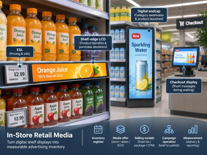
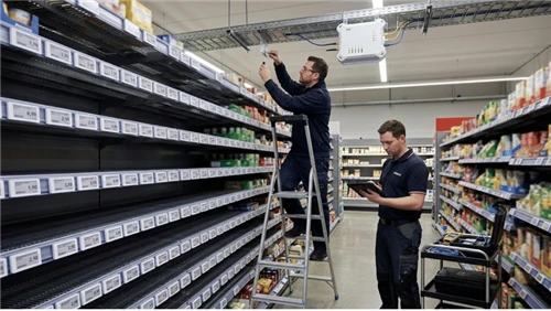
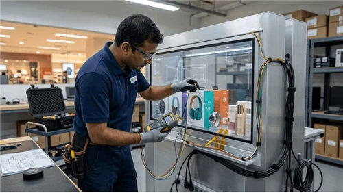
A long row of Bar LCD displays can work perfectly on a bench and still reset, dim, reboot, or drop offline after it is installed on a retail shelf. The usual reason is not that every screen is defective. It is that the power architecture was treated as a collection of adapters instead of one distributed electrical system.
For a multi-screen shelf run, the design has to answer four questions together: how much current the complete row needs in normal operation, what happens when several loads start at once, how much voltage is lost between the supply and each display, and whether one wiring or connector fault can take down the entire run. The correct limits come from the exact display, power-supply, connector, and cable documentation used in the released configuration. This guide focuses on the method for designing and validating that system rather than inventing one universal voltage, current, cable length, or display count.
If you are still choosing the display platform, start with the Bar LCD display range. Once the display family and mounting concept are fixed, use the process below to design the power distribution around the actual installation.

Choose the power architecture before you size anything
Power calculations only make sense after the topology is defined. Three arrangements are common in long retail fixtures, and each moves the electrical risk to a different place.
| Architecture | Where it helps | Main design risk |
|---|---|---|
| Individual AC/DC adapter per display | Simple replacement and short low-voltage leads | Many adapters, outlets, heat sources, and simultaneous AC-input inrush events |
| One centralized DC supply feeding a long trunk | Fewer supplies and easier centralized monitoring | Highest current near the supply, accumulated voltage drop, connector loading, and larger fault domain |
| Zoned supplies with several shorter DC branches | Balances serviceability, cable length, and fault isolation | More design interfaces and the need to document which screens belong to each zone |
There is no universally superior topology. A short two-screen fixture may not need the same architecture as a long aisle with many shelf displays. The decision should be based on the number of loads, route length, service access, available AC points, enclosure temperature, restart behavior, and the consequence of losing one power zone.
Do not treat grounding and ESD behavior as a side effect of this decision. Changing from individual adapters to a centralized supply can change chassis references and common-mode paths. Those issues belong in a separate Bar LCD ESD and grounding review, while this page remains focused on load current, startup behavior, voltage delivery, and fault containment.
Build the load budget from the exact released configuration
Start with the electrical input requirements of each display and any locally powered player, controller, converter, sensor, or accessory that shares the branch. Do not use a generic power value from another model or a family-level marketing page. If a power field is ambiguous or two documents disagree, ask the supplier to clarify the exact production revision before using the value as a design input.
The steady-state budget is the sum of the loads that can operate at the same time. That is only the first layer. The supply and distribution path must also survive the transient states that occur during startup, recovery, and mode changes.
Separate continuous current from startup current
A useful worksheet should record, for every load:
- approved input-voltage range for the exact hardware revision;
- normal and worst-case operating current or power from the model documentation;
- startup or peak-current information when the supplier provides it;
- whether the load starts immediately with power or can be sequenced;
- which power zone and connector path feeds it; and
- which operating condition represents the project worst case.
Do not assume that a power supply with a continuous rating above the arithmetic sum of the loads will automatically start the system. A supply can be within its steady-state rating and still enter current limit, hiccup, foldback, or another protection mode while several capacitive loads are charging. Texas Instruments explains the underlying mechanism: when voltage is first applied, charging capacitance can create an inrush current large enough to pull down the source rail if it is not controlled. See TI's Managing Inrush Current application note for the general power-electronics principle.
Do not confuse AC-input inrush with DC-load inrush
A multi-screen installation can contain two different startup events.
- AC-input inrush occurs when one or more AC/DC power supplies are energized and their input capacitors charge.
- DC-load inrush occurs when the displays, converters, players, or other downstream electronics charge their input capacitance from an already energized DC rail.
The distinction matters because the corrective action is different. Staggering AC/DC supplies may reduce a simultaneous mains-side event, while it may do nothing for a downstream DC branch that still connects several loads at once. Conversely, a DC soft-start or staged branch enable does not change the input inrush of an upstream supply when that supply itself is switched on.
Power-supply manufacturers commonly publish startup and inrush behavior for specific models. For example, MEAN WELL's display-power guidance notes that multiple supplies starting at the same time can create a much larger aggregate input-inrush event. Treat such guidance as a reminder to check the selected supply's actual datasheet and protection behavior, not as a universal Bar LCD specification.
Calculate voltage drop by segment, not by total cable length
The basic relationship is simple: voltage drop across a conductor path is current multiplied by the resistance of that path. The mistake in a long shelf run is assuming that the same current flows through every section.
In a daisy-chained trunk, the section closest to the supply carries the current for all downstream displays. After the first branch, the trunk current falls. After the second branch, it falls again. The far-end voltage is therefore the sum of the drop across each segment:
Far-end voltage drop = Σ(segment current × segment loop resistance)
Loop resistance includes the outgoing and return conductors plus relevant connector, terminal, and contact resistance. It should come from the actual cable specification, measured production assembly, or another controlled engineering source. Connector resistance and service joints matter because a small additional resistance becomes more significant as current rises.
Illustrative distributed-load example
The following values are deliberately hypothetical. They show the calculation method, not a KioskTagScreen product specification.
| Shelf segment | Loads still downstream | Segment current | Segment loop resistance | Voltage drop in segment |
|---|---|---|---|---|
| Supply to display 1 | 4 displays | 4 A | 0.04 Ω | 0.16 V |
| Display 1 to display 2 | 3 displays | 3 A | 0.04 Ω | 0.12 V |
| Display 2 to display 3 | 2 displays | 2 A | 0.04 Ω | 0.08 V |
| Display 3 to display 4 | 1 display | 1 A | 0.04 Ω | 0.04 V |
In that example, the calculated far-end drop is 0.40 V. The important lesson is not the number; it is that the first segment contributes the most drop because it carries the current of all four loads. If every display drew twice the current, the drop in this simplified example would also double. If connector resistance rises after service or contamination, the field result can be worse than the original cable-only calculation.
Analog Devices describes the same general problem in remote power delivery: greater cable resistance, greater distance, or greater load current increases the difference between regulator voltage and the voltage actually seen at the load. See its design note on remote-load voltage regulation for background on this relationship.
Measure the voltage where the display actually receives power
Do not approve a long shelf run from the power-supply terminals alone. Record the source voltage and the voltage at representative loads, especially the farthest display and any display behind the highest-resistance connector path. Perform the measurement in the installed wiring configuration with the production-equivalent load active.
The pass condition should be derived from the exact display input-voltage requirement and the approved engineering margin. A generic percentage such as "keep voltage drop under X%" is not a substitute for the product's actual minimum input requirement, supply tolerance, cable temperature, connector behavior, and startup transient.

Use topology to reduce current concentration and fault scope
When a single long trunk produces too much drop or puts excessive current through early connectors, the solution is not automatically a larger power supply. The supply may already have enough watts while the distribution path remains the limiting element.
Useful architecture changes can include:
- splitting one long trunk into two or more shorter branches;
- placing zoned supplies closer to the loads;
- using a heavier conductor or lower-resistance distribution path where justified;
- avoiding connector chains that force total downstream current through a contact intended for one device;
- providing individually serviceable branches instead of hiding every load behind one inaccessible harness; and
- using branch protection and isolation appropriate to the released electrical design.
Any conductor, terminal, fuse, breaker, connector, distribution board, or supply should be selected against its own rating, installation conditions, and applicable electrical requirements. This article does not provide conductor ampacity, fuse, or mains-branch values because those depend on the exact hardware and installation jurisdiction and should be handled by qualified electrical personnel.
Design startup so one transient does not become a shelf-wide reset
Startup is where a marginal system often reveals itself. Several screens that run normally after boot can all fail together when power is first applied.
Three behaviors deserve separate verification:
- Supply startup: Does the AC/DC supply reach regulation cleanly with the connected load, or does it enter overload protection and retry?
- Distribution-rail response: Does the DC rail dip when multiple display inputs charge, and how quickly does it recover?
- Load recovery: If voltage momentarily falls, do displays and players recover automatically, or can one device remain latched in a failed state?
Where the chosen hardware supports controlled sequencing, staged startup can reduce simultaneous demand. It should not be added blindly: the sequence itself becomes part of the approved configuration and must still recover after a real power interruption. A system that only starts correctly after a manual technician sequence is not an acceptable automatic-recovery design unless that operating constraint is explicitly intended.
Temperature can also change startup behavior. If the installation is exposed to cold storage, vestibules, refrigerated aisles, or another demanding environment, keep temperature-transition testing with the separate commercial LCD cold-start and temperature-cycling guide rather than turning this power-distribution page into an environmental qualification article.
Protect the distribution path without creating a single failure domain
A centralized supply can simplify maintenance, but it can also make one fault more consequential. If every display is on one unsegmented output, a damaged cable or failed device can affect the whole row depending on the supply's protection behavior.
The design review should answer:
- What happens if one branch becomes overloaded or shorted?
- Does the complete output shut down, current-limit, retry, or isolate the affected branch?
- Can a technician disconnect one display without disturbing neighboring screens?
- Are connectors and distribution points accessible for inspection and replacement?
- Can the system identify which zone failed, or does every fault look like "all screens off"?
Fault-containment tests should be performed with purpose-built, current-limited, or otherwise protected test methods by qualified personnel. Do not create uncontrolled shorts on an energized retail installation. The purpose is to prove the released protection architecture and recovery behavior, not to improvise a destructive test.
Commission the actual shelf run, not a short bench cable
Final acceptance should use the installed or production-equivalent cable route, connectors, power supply, distribution hardware, displays, and any devices that share the rail. A short bench harness can prove that the display powers on; it cannot prove the long-run distribution design.
Minimum commissioning sequence
- Document the baseline. Record display quantity and revision, supply model, distribution topology, cable/harness revision, connector path, and branch mapping.
- Measure steady-state load. Run the approved worst-case operating mode and record supply output current plus load voltage at representative near and far positions.
- Capture simultaneous cold start. Verify that the supply reaches regulation, the rail does not collapse outside the allowed load condition, and every display reaches its intended state.
- Repeat with realistic restart orders. Test full power restoration, a single zone restart, and any service reconnection sequence that can occur in the field.
- Verify branch isolation. Use a safe protected method to confirm that the defined fault domain and recovery behavior match the design.
- Observe the installed thermal condition. Confirm that supplies, connectors, and distribution hardware are not being evaluated in an unrealistically open bench environment. Detailed heat-path design belongs in the Bar LCD thermal-management guide.
Use the right instrument for the time scale
A digital multimeter is useful for steady DC voltage and can reveal persistent far-end drop. It may not capture a short startup dip. When the decision depends on a transient event, use measurement equipment with enough bandwidth and sampling capability for that event, such as a properly rated oscilloscope and current probe, and follow the instrument and electrical-safety requirements for the circuit being measured.
Preserve the waveform or log when a startup problem is intermittent. "It worked on the second try" is recovery evidence, not proof that the original power path was correct.

Troubleshoot by where the symptom appears
| Observed symptom | First areas to check | Why it points there |
|---|---|---|
| All screens reset together at power-on | Supply startup, aggregate inrush, current-limit behavior, upstream AC-input inrush if multiple supplies start together | The event is synchronized across the shared source |
| Far-end screens reset or dim under heavy load while near screens remain stable | Trunk resistance, connector resistance, branch current, far-end input voltage | Voltage drop increases along the shared path |
| One display is intermittent while neighbors are stable | Local connector, tap, cable, branch protection, device input | The fault is likely downstream of the shared portion |
| One display fault blanks the entire row | Protection architecture and fault-domain design | The distribution system is not isolating the affected branch |
| Power supply repeatedly starts and stops | Overload protection, capacitive load, startup sequencing, wiring fault, thermal protection | Many supplies retry when the output cannot establish a stable operating state |
| Problem begins after service or fixture change | Connector seating, harness revision, added resistance, branch mapping, changed supply or adapter | The approved electrical path may no longer match the commissioned configuration |
If the fault appears to be caused by mains surge, harmonics, power factor, or building-circuit planning rather than the low-voltage shelf distribution itself, transfer that investigation to the separate commercial LCD power-quality guide. Likewise, faults caused by ESD or bonding should remain with the dedicated grounding page. Keeping those boundaries clear makes each incident easier to diagnose.
Supplier and integrator data that should be locked before rollout
A useful RFQ or engineering handoff does not ask whether the system "supports multiple screens." It asks for the inputs needed to validate the released architecture.
- Exact display model and hardware revision.
- Documented input-voltage range and normal/worst-case power data for that revision.
- Startup or peak-current information when available.
- Approved power-supply model, rating, protection behavior, and environmental derating information.
- Connector and distribution-hardware ratings for the actual current path.
- Cable/harness type, resistance data, branch length, and allowed substitutions.
- Whether simultaneous start, staged start, or another recovery behavior is required.
- Which component changes require the power-distribution test to be repeated.
If a required value is not available, do not replace it with a number copied from another Bar LCD model. Mark it as an engineering input that must be confirmed before the final branch count, cable choice, or power-supply capacity is approved.
Approval checklist for a multi-screen shelf run
- The power topology is documented: individual, centralized, or zoned.
- The load budget uses the exact released models and includes startup behavior where it can affect the result.
- AC-input inrush and DC-load inrush are treated as different events.
- Voltage drop is calculated segment by segment for shared trunks.
- The nearest and farthest representative displays are measured under production-equivalent load.
- Connectors and distribution points are checked for the current they actually carry, not just the current of one screen.
- The design contains a defined fault domain and service-isolation method.
- Simultaneous cold start and recovery after real power interruption are tested.
- Thermal, ESD/grounding, and building-power-quality issues are handed to their own engineering owners rather than duplicated here.
- Supplier substitutions, cable changes, branch-count changes, and power-supply replacements have explicit retest rules.
A reliable Bar LCD shelf run is not created by choosing the largest available power supply. It is created by matching the supply, distribution path, branch topology, connector path, startup behavior, and acceptance test to the installed system. When those elements are measured as one electrical chain, nuisance resets and far-end instability become diagnosable engineering problems instead of unexplained field failures.
If you are preparing a custom shelf installation, bring the display quantity, proposed topology, supply location, longest branch, and confirmed model power data when you request a project quotation. Those inputs make the electrical scope much easier to review before hardware is released.