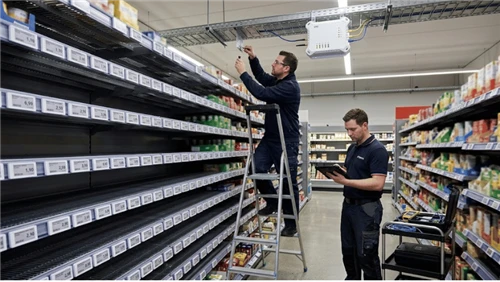
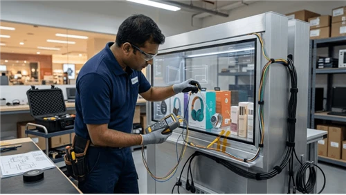
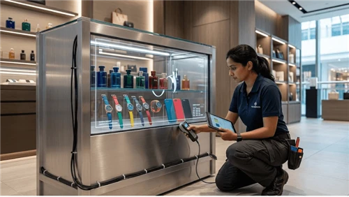
This is a narrow engineering topic with an outsized effect on field reliability because several teams own different pieces of the same result. Analyze the complete shelf installation: display chassis, metal rail, brackets, protective earth where applicable, signal shields, power supplies, and user-accessible discharge paths. This guide is written for Electrical engineers, EMC teams, fixture designers, integrators, and quality teams. Its practical question is straightforward: How should a bar LCD installed on metal retail fixtures be bonded and tested for ESD robustness? The answer is not a universal number or a one-line product claim. It is a controlled method that defines the operating condition, the configuration being approved, the evidence required for acceptance, and the conditions that force a retest.
Commercial and bar-format LCD projects combine a panel, enclosure, mounting system, player or source, power, control interfaces, content, and a retail fixture. Acceptance must therefore be tied to the installed assembly rather than to a panel headline specification. For that reason, this article treats bar LCD ESD grounding as a system decision. Exact limits-such as electrical ratings, optical tolerances, mechanical loads, environmental severities, safety limits, communication timing, or maintenance intervals-must come from the exact production model, applicable standards, and the buyer's approved project requirements. Where those sources do not establish a universal value, this guide deliberately does not invent one.

Before freezing the specification, keep the topic connected to the wider LEGOYO content architecture. Useful starting points are Bar LCD Display Screen, Bar LCD CMS Integration, Bar LCD Thermal Management. Those pages establish the product and adjacent-system boundary; this article owns the narrower problem described above rather than repeating their broader material.
For content-gap research, the planning review compared how Samsung Business Displays, LG Commercial Display, Orient Display present the broader product category. Those commercial sources informed topic differentiation only; the final article does not use competitor marketing claims as project facts or link readers to competing commercial pages.
Define the decision boundary before choosing a fix
The first deliverable should be a one-page decision boundary for bar LCD ESD grounding. It should identify the exact site/use case, the production hardware and software revision, who operates the feature, what failure looks like to that user, and what evidence is required before the design can be accepted. This avoids a common B2B procurement failure: comparing attractive component features before agreeing what the installed display installation must actually do.
For this topic, explicitly include chassis and bracket electrical continuity, protective-earth strategy where required by the product design, metal shelf and fixture bonding, signal shield termination. Then add power-supply grounding topology, ESD paths from accessible bezel/rail areas, cable routing relative to noisy or exposed conductors, service reassembly of bonding hardware. These are not independent checklist items. A change to one can invalidate the others. The project record should therefore tie each condition to an owner and a retest trigger.
Minimum scope record
- Exact production model, revision, accessory/fixture configuration, and software/firmware versions relevant to bar LCD ESD grounding
- Defined users and normal workflow, including who handles exceptions and service
- Site/environment assumptions that can change the result
- Interfaces to adjacent systems, devices, content, power, network, fixtures, or data sources
- Acceptance method and evidence owner for every critical requirement
- Change triggers that require comparison with the approved baseline or a formal retest
The scope should also say what this article does not own. LEGOYO has kiosk ESD content, but no dedicated bar-LCD/metal-shelf grounding article was found. Keeping that boundary explicit reduces cannibalization in the content strategy and, more importantly, prevents engineering teams from using one test as evidence for a different risk.
Map the installed system and its interfaces
Draw the path from trigger or source through the hardware/software stack to the result a user can observe. For bar LCD ESD grounding, the drawing should be specific enough that a technician can point to where a fault could be introduced and where it can be measured. Avoid a marketing architecture with only cloud, device, and user icons; the useful drawing includes the interfaces that can create ambiguous ownership.
A practical interface map for this project includes the following control points. The evidence column is deliberately generic because the exact tool depends on the production design; the important requirement is that the team chooses a repeatable method before acceptance.
| Control point | What must be defined | Useful evidence |
|---|---|---|
| Chassis and bracket electrical continuity | Define the production condition and its owner. | Record observable state, configuration, and exception evidence. |
| Protective-earth strategy where required by the product design | Define the production condition and its owner. | Record observable state, configuration, and exception evidence. |
| Metal shelf and fixture bonding | Define the production condition and its owner. | Record observable state, configuration, and exception evidence. |
| Signal shield termination | Define the production condition and its owner. | Record observable state, configuration, and exception evidence. |
| Power-supply grounding topology | Define the production condition and its owner. | Record observable state, configuration, and exception evidence. |
| ESD paths from accessible bezel/rail areas | Define the production condition and its owner. | Record observable state, configuration, and exception evidence. |
| Cable routing relative to noisy or exposed conductors | Define the production condition and its owner. | Record observable state, configuration, and exception evidence. |
| Service reassembly of bonding hardware | Define the production condition and its owner. | Record observable state, configuration, and exception evidence. |
Once the map exists, assign a named owner to every boundary: OEM hardware, fixture/mechanical design, electrical integration, platform/software, store operations, service, and procurement acceptance as applicable. Many costly field faults persist because each team can prove its own component is working while nobody owns the end-to-end outcome.
Configuration identity matters
Always record the configuration that produced a pass. At minimum, capture the hardware revision, connected accessories, relevant cable/fixture version, firmware and software, settings that affect the behavior, and site condition. If a supplier substitutes a part or the field team changes a route, bracket, controller, player, driver, template, or setting, the project should be able to tell whether the original evidence still applies.
Design controls worth specifying explicitly
A strong specification for bar LCD ESD grounding should convert the following topics from assumptions into controlled requirements. Each control needs a normal state, an exception state, evidence, and a change trigger.
Chassis and bracket electrical continuity
Treat chassis and bracket electrical continuity as an interface, not a label in a drawing. State what establishes the approved condition, what downstream behavior depends on it, and how a technician can verify it on production-equivalent equipment. Then test its interaction with protective-earth strategy where required by the product design because that neighboring condition can change the result without producing an obvious hardware alarm.
For procurement, ask for the model-specific boundary and supporting documentation. For commissioning, add local evidence. A supplier document can establish what a product was designed to support; it cannot prove that the buyer's exact fixture, data, software, environment, content, and operating workflow have been integrated correctly.
Protective-earth strategy where required by the product design
Treat protective-earth strategy where required by the product design as an interface, not a label in a drawing. State what establishes the approved condition, what downstream behavior depends on it, and how a technician can verify it on production-equivalent equipment. Then test its interaction with metal shelf and fixture bonding because that neighboring condition can change the result without producing an obvious hardware alarm.
For operations, make abnormal state visible. A resilient design should not require store staff to infer whether a system is healthy from customer complaints. Provide a diagnostic state or record that distinguishes configuration error, unavailable dependency, service condition, and a genuine component fault wherever the technology allows it.

Metal shelf and fixture bonding
Treat metal shelf and fixture bonding as an interface, not a label in a drawing. State what establishes the approved condition, what downstream behavior depends on it, and how a technician can verify it on production-equivalent equipment. Then test its interaction with signal shield termination because that neighboring condition can change the result without producing an obvious hardware alarm.
For procurement, ask for the model-specific boundary and supporting documentation. For commissioning, add local evidence. A supplier document can establish what a product was designed to support; it cannot prove that the buyer's exact fixture, data, software, environment, content, and operating workflow have been integrated correctly.
Signal shield termination
Treat signal shield termination as an interface, not a label in a drawing. State what establishes the approved condition, what downstream behavior depends on it, and how a technician can verify it on production-equivalent equipment. Then test its interaction with power-supply grounding topology because that neighboring condition can change the result without producing an obvious hardware alarm.
For operations, make abnormal state visible. A resilient design should not require store staff to infer whether a system is healthy from customer complaints. Provide a diagnostic state or record that distinguishes configuration error, unavailable dependency, service condition, and a genuine component fault wherever the technology allows it.
Power-supply grounding topology
Treat power-supply grounding topology as an interface, not a label in a drawing. State what establishes the approved condition, what downstream behavior depends on it, and how a technician can verify it on production-equivalent equipment. Then test its interaction with ESD paths from accessible bezel/rail areas because that neighboring condition can change the result without producing an obvious hardware alarm.
For procurement, ask for the model-specific boundary and supporting documentation. For commissioning, add local evidence. A supplier document can establish what a product was designed to support; it cannot prove that the buyer's exact fixture, data, software, environment, content, and operating workflow have been integrated correctly.
ESD paths from accessible bezel/rail areas
Treat ESD paths from accessible bezel/rail areas as an interface, not a label in a drawing. State what establishes the approved condition, what downstream behavior depends on it, and how a technician can verify it on production-equivalent equipment. Then test its interaction with cable routing relative to noisy or exposed conductors because that neighboring condition can change the result without producing an obvious hardware alarm.
For operations, make abnormal state visible. A resilient design should not require store staff to infer whether a system is healthy from customer complaints. Provide a diagnostic state or record that distinguishes configuration error, unavailable dependency, service condition, and a genuine component fault wherever the technology allows it.
Cable routing relative to noisy or exposed conductors
Treat cable routing relative to noisy or exposed conductors as an interface, not a label in a drawing. State what establishes the approved condition, what downstream behavior depends on it, and how a technician can verify it on production-equivalent equipment. Then test its interaction with service reassembly of bonding hardware because that neighboring condition can change the result without producing an obvious hardware alarm.
For procurement, ask for the model-specific boundary and supporting documentation. For commissioning, add local evidence. A supplier document can establish what a product was designed to support; it cannot prove that the buyer's exact fixture, data, software, environment, content, and operating workflow have been integrated correctly.
Service reassembly of bonding hardware
Treat service reassembly of bonding hardware as an interface, not a label in a drawing. State what establishes the approved condition, what downstream behavior depends on it, and how a technician can verify it on production-equivalent equipment. Then test its interaction with chassis and bracket electrical continuity because that neighboring condition can change the result without producing an obvious hardware alarm.
For operations, make abnormal state visible. A resilient design should not require store staff to infer whether a system is healthy from customer complaints. Provide a diagnostic state or record that distinguishes configuration error, unavailable dependency, service condition, and a genuine component fault wherever the technology allows it.
Failure modes to design for before rollout
The following failures are intentionally more specific than "device not working." They represent plausible ways a bar LCD ESD grounding project can be technically connected but operationally wrong. Use them as FMEA inputs, pilot scenarios, and support-ticket categories; do not treat the table as a claim that every product will experience every condition.
| Failure mode | Detection principle | Required response |
|---|---|---|
| A painted bracket interrupts the intended chassis bonding path | Make the condition observable and preserve context. | Assign correction, owner, and targeted retest. |
| A service technician omits a bonding washer or strap and the unit becomes more susceptible after repair | Make the condition observable and preserve context. | Assign correction, owner, and targeted retest. |
| Multiple supplies and shield paths create unintended currents or noise problems | Make the condition observable and preserve context. | Assign correction, owner, and targeted retest. |
| ESD enters through an exposed shelf edge near the display and couples into signal or control cables | Make the condition observable and preserve context. | Assign correction, owner, and targeted retest. |
| A bench test passes because the display is isolated from the large metal fixture used in the store | Make the condition observable and preserve context. | Assign correction, owner, and targeted retest. |
| Fixture changes move or remove the path assumed during the original EMC test | Make the condition observable and preserve context. | Assign correction, owner, and targeted retest. |
A useful failure response protects the next transaction or store task, exposes the condition to the correct owner, and preserves enough evidence to diagnose it. "Reboot until it works" may temporarily restore service but destroys information about cause and can hide systematic faults. Where reboot or reset is an approved recovery action, log why it was used and whether the fault returned.
Separate symptom, cause, and consequence
For bar LCD ESD grounding, a visible symptom can have causes in hardware, installation, software, data, content, environment, or service. The incident record should therefore capture the symptom seen by the user, the system state at that moment, recent changes, the diagnostic finding, and the final corrective action. This makes recurring "random" failures comparable across sites instead of producing isolated anecdotes.
Build an acceptance test that represents the field
Acceptance testing should prove the workflow described by How should a bar LCD installed on metal retail fixtures be bonded and tested for ESD robustness? Start with a known-good production configuration, capture the baseline, then introduce one controlled variation or failure at a time. Do not approve the project solely because the normal demo path works once.
| Step | Test activity | Evidence to retain |
|---|---|---|
| 1 | Create a grounding/bonding drawing for the production fixture rather than relying on schematic assumptions | Configuration, expected result, actual result, evidence, owner, disposition |
| 2 | Measure continuity at defined serviceable joints using a project-approved method | Configuration, expected result, actual result, evidence, owner, disposition |
| 3 | Exercise representative accessible discharge points on the production-equivalent fixture under the applicable EMC test plan | Configuration, expected result, actual result, evidence, owner, disposition |
| 4 | Monitor display image, control, network, touch, player, and power behavior during and after disturbances | Configuration, expected result, actual result, evidence, owner, disposition |
| 5 | Remove and reinstall one unit using the service procedure and verify the intended bonding path is restored | Configuration, expected result, actual result, evidence, owner, disposition |
| 6 | Document deviations between formal compliance testing and site-level engineering checks so neither is misrepresented as the other | Configuration, expected result, actual result, evidence, owner, disposition |
Factory, site, and pilot tests do different jobs
Factory acceptance is useful for repeatable configuration checks, controlled fault injection, assembly review, and supplier evidence. Site acceptance exposes real mounting, power, lighting, RF, network, store fixtures, access, cleaning, and operator conditions. A pilot adds time: shift changes, replenishment, maintenance, content or data changes, peak periods, replacement parts, and real exception ownership. Reuse the same requirement IDs across all three stages so evidence remains traceable.
Do not average away a serious failure
A high overall pass percentage can hide an unacceptable edge case. Classify requirements by consequence before testing. A rare defect that can misidentify a product, interrupt a transaction, strand a customer document, create an electrical/EMC problem, or silently desynchronize operations may justify a stronger control than a more frequent cosmetic defect. The project should decide that priority before test results are known.
Retest the neighbors after a fix
When a defect is corrected, rerun the failed case and the neighboring cases the change could affect. A new bracket can change RF; a new seal can change temperature; a new driver can change enumeration; a new template can change scan layout; a new timing rule can change recovery. Closing only the original symptom is not sufficient when the fix crosses an interface.
Procurement questions that expose hidden scope
For bar LCD ESD grounding, a useful RFQ asks the supplier to state the exact configuration and evidence boundary. Avoid yes/no questions such as "supported?" when the real issue is how the function behaves in the buyer's installed system.
- What grounding and bonding requirements apply to the exact display and power configuration?
- Which brackets, washers, straps, or conductive finishes are part of the approved assembly?
- What EMC/ESD evidence is available for the exact model and what fixture boundary did it cover?
- Are signal-shield termination recommendations provided for the project interfaces?
- Which installation changes require renewed EMC review?
- How should bonding integrity be checked after service?
Ask the supplier to mark each response as standard, optional, integrator-supplied, buyer-supplied, or project-specific engineering. Request drawings and documentation that match the quoted revision. If the answer depends on site conditions, the dependency should be written into the quote or technical schedule instead of left as a sales-call assumption.
Normalize quotations before comparing price
Two quotations are not comparable when one includes fixtures, cables, licensed software, commissioning, diagnostic access, spares, and training while another assumes the buyer will provide them. Build a compliance matrix with requirement ID, supplier response, evidence, deviation, owner, and commercial impact. This is especially important for integrated retail hardware because the missing item often appears later as site labor or custom engineering rather than as a visible line in the hardware price.

Operations and change control after handover
A passing installation can drift. For bar LCD ESD grounding, the handover package should include the approved configuration, relevant drawings, test records, known failure symptoms, recovery actions, service access instructions, and a clear list of changes that require renewed verification. Store layout changes, replacement parts, firmware/software updates, cleaning processes, cabling changes, and local configuration edits are common sources of drift.
Metrics worth trending
- grounding defects found during service audits
- ESD-related resets or control faults by fixture type
- missing/loose bonding hardware
- repeat faults after display replacement
- site modifications affecting metal continuity
Trend exceptions by site, hardware/software revision, fixture family, service action, and time. The purpose is not to create a dashboard for its own sake; it is to detect patterns that a single help-desk ticket cannot show. If a particular replacement part, store fixture, or software release appears repeatedly, the issue can be moved from reactive support into change control.
Adjacent LEGOYO guidance that can help maintain the wider system boundary includes Shelf-Edge LCD Content Design, LCD Image Retention Prevention, Commercial Display vs Consumer TV, Products. Use those pages for neighboring decisions rather than expanding this article until it competes with them.
Retest triggers to place in the handover
- Hardware or accessory revision changes the approved assembly
- Firmware, operating system, driver, CMS, application, API, or template change can affect the tested behavior
- Fixture, mounting, lighting, power, network, RF, cleaning, airflow, or service condition changes
- A substitute component is introduced because the original reaches end of life
- A recurring field failure challenges an assumption used during initial acceptance
Decision framework: approve, revise, or stop
| Decision layer | Required artifact | Approval question |
|---|---|---|
| Scope | Use case, site, users, exact configuration | Is the boundary explicit enough to reproduce? |
| Design | Interface map and controlled requirements | Does every critical assumption have an owner? |
| Evidence | Production-equivalent test records | Can another reviewer understand why it passed? |
| Recovery | Detection, degraded state, service action | Can operators recognize and recover from abnormal states? |
| Lifecycle | Baseline, revisions, spares, retest triggers | Can the approved state be maintained after handover? |
For bar LCD ESD grounding, the final status should be approve, revise, or stop-not "looks fine." Record residual risks and their owner. If an item cannot be proven before rollout, state the temporary control and the date/event when evidence will be collected. This prevents an unresolved pilot assumption from silently becoming the production standard.
The strongest next step is to give the supplier the site conditions, interface map, intended workflow, and acceptance evidence you expect. If you are evaluating a LEGOYO project, use Request a Quote after those inputs are ready; a more complete requirement set makes configuration review and quotation comparison more useful.
FAQ
Q: Can a supplier data sheet alone prove bar LCD ESD grounding is acceptable?
A: No. A data sheet can establish model-specific boundaries, but the project must still verify the installed interactions that matter to the intended workflow. Use supplier documentation as an input to the acceptance plan, not as a substitute for it.
Q: How large should the pilot be?
A: There is no universal device count. Choose a pilot large and varied enough to include the difficult conditions that could change the result: representative fixtures, edge locations, user behaviors, operating states, service actions, and failure recovery. A smaller pilot with deliberately selected risk cases can be more useful than a larger convenience sample.
Q: What should trigger a retest of chassis and bracket electrical continuity?
A: Retest when a change can affect the approved condition, including a model or revision substitution, changes to protective-earth strategy where required by the product design, metal shelf and fixture bonding, software/firmware, mounting, site environment, or a recurring field failure. The handover record should name these triggers before the project closes.
Q: How should acceptance evidence be stored?
A: Keep the requirement ID, exact configuration, method, expected result, actual result, evidence location, reviewer, defect disposition, and date together. Screenshots or photographs without configuration context are weak evidence; logs without a physical/site reference can be equally ambiguous.
Q: Should every store use the same threshold?
A: Use common definitions and methods where possible, but do not copy a threshold into a different risk or environment without justification. Exact numerical limits should come from applicable standards, model-specific documentation, validated project requirements, or approved pilot evidence-not from an unrelated example.
Final recommendation
Treat bar LCD ESD grounding as a controlled project boundary rather than a feature claim. Define the exact production configuration, make failure observable, test the hard conditions deliberately, and carry the approved state into service and change control. That approach is slower than a showroom checkbox at the beginning, but it is far faster than diagnosing an ambiguous fleet problem after rollout.
For product context, return to LEGOYO products or the technical blog. For a project-specific review, prepare your site conditions, interfaces, workflow, and acceptance criteria before using Request a Quote.