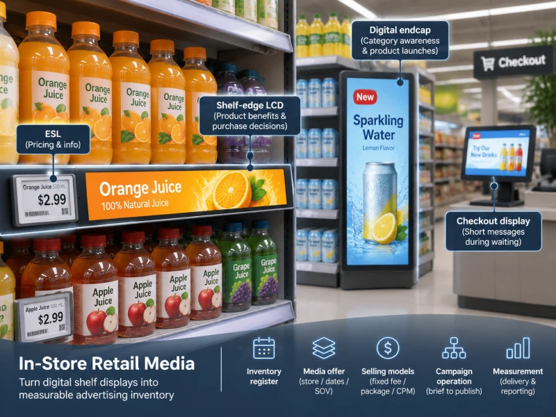
Small color differences become much more visible when several bar LCDs sit side by side on the same shelf run. One screen can look slightly cooler, another can be brighter, and a third can lose shadow detail even though all three are showing the same file. A row that should read as one continuous digital surface instead looks like separate panels.
The solution is not to copy one screen's picture settings to every other unit or to match them by eye under changing store light. Multi-screen color matching is a measurement problem: characterize each installed display, choose a target the group can actually achieve, normalize the signal path, calibrate the relevant controls, and verify the result with repeatable measurements and representative content.
This guide focuses on adjacent bar and stretched LCDs used as a coordinated shelf display. It does not define a universal white point, luminance, gamma value, or color-difference limit. Those targets depend on the content workflow, hardware capabilities, ambient environment, viewing geometry, and project acceptance criteria.
Start by defining what "matched" needs to mean
Not every multi-screen installation needs the same level of optical matching. The acceptance target should follow the visual job.
| Display relationship | What usually matters most | Why |
|---|---|---|
| One panoramic image or animation spans adjacent screens | White point, luminance, grayscale/tone response, and visible seam consistency | Any jump between screens interrupts one continuous image |
| Each screen shows separate content, but all screens are visible together | White point and broad luminance consistency | The screens should look like one fixture even when content differs |
| Screens sit in visibly different lighting zones | Project-defined visual consistency under the installed environment | Identical measured output may not produce identical perceived appearance |
| One screen is a replacement in an established run | Match to the retained approved baseline or re-characterize the group | The replacement may have different native output or control behavior |
This distinction prevents a common mistake: using a color-calibration target that is technically precise but unrelated to the actual visual requirement. Sharp's Display Wall Calibrator, for example, distinguishes between matching both white point and luminance across displays and matching white point while allowing each display to operate at a different achievable intensity. Its broader point is useful beyond video walls: decide what must match before you decide how to calibrate it.
For a continuous shelf panorama, matching only the color of full white is usually too narrow. The handoff between screens can still be obvious in mid-grays, dark detail, gradients, product photography, or brand colors if their tone responses differ.
Measure every screen before choosing the group target
Do not assume that the first screen installed should become the master. First characterize all displays in the production-equivalent run using the same measurement method. Record at least the quantities that matter to the project: white luminance, white chromaticity, several neutral gray levels, and any relevant black or near-black behavior that the instrument and installation can measure reliably.
The measurements answer two different questions:
- How different are the screens before correction?
- What common target can all of them reach without pushing one unit outside a stable operating range?
Sharp's official multi-display calibration material describes the same basic constraint: when displays must match in both color and intensity, the achievable wall target is limited by the least-capable display in the group. In practical terms, raising three screens to a target that one unit cannot reach is not color matching; it is a specification mismatch.
The common target can therefore be based on the project content standard, an approved reference display, or a value derived from the measured capability of the group. The important requirement is that the target be deliberate and documented. If one screen is materially outside the rest of the population, investigate the unit, panel revision, picture mode, backlight behavior, or signal path before forcing the other screens to match it.

Freeze the signal path before touching calibration controls
Color matching fails quickly when two screens are not receiving or interpreting the same signal. Before adjusting white point or luminance, verify that each path is functionally equivalent.
| Signal/control item | What to verify | Failure symptom |
|---|---|---|
| Source content | Same test file, frame, color encoding, and rendering path | Different source transforms are mistaken for panel variation |
| Player output | Same resolution, refresh mode, RGB/YCbCr choice where applicable, and range handling | One screen has lifted blacks, clipped highlights, or different neutral tones |
| Display input | Same intended input and input-specific picture configuration | A calibrated HDMI input looks different when a replacement boots to another input |
| Picture mode | Same approved base mode or documented device-specific baseline | Controls behave differently even when their numeric values look identical |
| Dynamic processing | Disable or standardize dynamic contrast, adaptive color, eco dimming, local enhancements, or similar processing where they interfere with repeatable measurement | Readings change with test content or time |
| Firmware / hardware revision | Record revisions that can change picture controls or output | A replacement cannot reproduce the original screen's response |
Do not blindly copy numeric OSD values from one screen to another. The same backlight, RGB gain, or gamma setting does not guarantee the same measured output across panels. Copying settings is a configuration shortcut; matching output requires measurement.
Once the approved picture state is established, the site's commercial LCD configuration baseline guide is the appropriate owner for locking settings, backup, drift detection, and replacement commissioning. This page remains focused on establishing the optical match itself.
Use one measurement protocol for every screen
A repeatable calibration procedure controls the measurement conditions as carefully as the display settings. If screen A is measured in the center with one sensor orientation and screen B is measured near the edge at another angle, the comparison includes measurement error as well as panel difference.
Define one protocol and use it across the run:
- stabilize the displays for the period recommended by the display or calibration-system supplier before taking final measurements;
- use the same measurement instrument, instrument mode, and correction method for every screen;
- measure the same screen location or the same defined set of locations;
- keep sensor contact, distance, and angle consistent;
- use the same test-pattern source and the same signal path;
- record the ambient condition when room or fixture lighting can affect the measurement or visual assessment;
- avoid applying pressure to an LCD surface in a way that can change the image locally.
A colorimeter is practical for repeated display measurements, while higher-accuracy workflows may use a spectroradiometer directly or to characterize/check the colorimeter. The project does not need to prescribe one instrument class for every installation, but it does need a traceable and repeatable method.
Also separate panel-to-panel matching from screen uniformity. A center-point measurement can show that two screens have the same center white, while their edges still differ. Sharp notes this limitation in its multi-display calibration guidance: local uniformity and viewing-angle effects can remain even after the measured points match. If adjacent screen edges are visually critical, include edge-area checks in the acceptance method instead of assuming a center reading proves the seam.
Calibrate in an order that avoids chasing coupled controls
Display controls interact. Changing white-point gains can change luminance; changing black-level or offset controls can alter the dark end of the grayscale; changing the tone-response setting can alter midtone appearance. A disciplined order reduces rework.
- Establish the approved base picture state. Confirm signal handling, picture mode, and dynamic-processing settings before measuring.
- Bring white luminance toward the common target. Use the supported backlight or luminance control rather than color gains when the hardware allows those functions to remain separate.
- Adjust white point at the bright end. Use the display's supported RGB gain, color-temperature, calibration-LUT, or equivalent controls.
- Check mid-gray and darker neutrals. If the hardware exposes offset/bias or a calibration LUT, correct neutral tracking without sacrificing the already-matched bright end.
- Verify the tone-response curve. Confirm that the screens render the same input levels similarly across the grayscale, not just at white.
- Re-measure luminance and white point. Changes in RGB balance or tone response can move the values adjusted earlier.
- Repeat only as needed. Iterate until the relevant metrics meet the project criteria and the screens remain visually coherent with real content.
Sharp's multi-display calibration system similarly treats intensity, white point, and grayscale/tone response as separate calibration characteristics. EIZO's calibration guidance also distinguishes white point, luminance, and gamma as separate adjustment targets. The practical lesson is that "brightness matched" is not the same as "color matched."

Verify the grayscale, not just a full-white patch
A row of screens can match at 100% white and still diverge through the rest of the image. One screen may be neutral in highlights but greenish in mid-gray. Another may compress dark tones. A third may use a different effective tone response that makes the same product image look flatter or more contrasty.
Use a neutral verification set that samples the usable range. The exact step count is project-specific, but a practical set includes bright white, several mid-gray levels, darker gray, and a neutral ramp. Then add representative production content such as:
- large areas of white or light neutral background that cross a seam;
- brand-neutral product photography with skin, packaging, or natural materials if relevant to the content plan;
- dark gradients or shadow detail;
- solid and gradient graphics that span two adjacent screens;
- the actual shelf campaign layout with its normal typography and background colors.
Do the instrument check first and the visual review second. Human observers are valuable for finding visible seams and context-specific problems, but the eye adapts to ambient light and surrounding color. Matching by eye alone makes the result difficult to reproduce during service or replacement.
Separate within-screen uniformity from between-screen consistency
There are two different optical problems in a multi-screen run:
- within-screen uniformity: one panel changes in brightness or color from center to edge;
- between-screen consistency: the measured and perceived output changes from one display to the next.
Calibration can improve the second problem without necessarily eliminating the first. If the right edge of screen A is warmer than its center while the left edge of screen B is cooler than its center, the joint can remain visible even when their center readings match.
That is why acceptance should include the viewing geometry that matters to the installed shelf. Check the run from the intended shopper or operator positions, not only straight on at each screen. LCD appearance can change with viewing angle, and a long shelf run naturally places the outer screens at different angles from the viewer.
Physical alignment is a separate owner. If the visual seam is caused by height steps, rotation, bezel gaps, shelf deflection, or a non-flat mounting rail, use the Bar LCD mechanical alignment guide rather than trying to correct a geometry problem with color settings.
Set project-specific acceptance tolerances instead of inventing universal numbers
There is no single tolerance that is automatically correct for every shelf run. A continuous luxury-brand visual, independent price-promotion strips, and utility information screens may justify different acceptance limits. Hardware capability, viewing distance, ambient light, and measurement uncertainty also matter.
A good acceptance specification defines the metric, the measurement condition, and the pass rule. It can include:
| Metric | What it reveals | How to specify it responsibly |
|---|---|---|
| White luminance difference | Visible brightness steps between screens | Define the reference level, measurement point, instrument, and allowed deviation for this project |
| White-point chromaticity or color difference | Cool/warm or tinted white mismatch | Define the color metric and target used by the project; do not mix incompatible metrics |
| Neutral grayscale tracking | Tint changes through highlights, midtones, and shadows | Define which gray levels are measured and whether limits apply per step or across a summary metric |
| Tone-response / gamma or EOTF deviation | Different contrast and midtone rendering | Use the response target required by the content workflow rather than assuming one generic gamma |
| Visual seam review | Problems not fully represented by one measurement point | Define approved content, viewing positions, ambient state, and reviewer method |
If the project uses a color-difference metric such as ΔE, name the exact formula and measurement basis. A number labeled only "ΔE" is incomplete because different formulas do not produce interchangeable values. The same discipline applies to luminance tolerance: state whether the comparison is against a reference display, the group mean, or a fixed target.
For projects where the main problem is absolute readability under strong ambient light rather than cross-screen matching, use the separate commercial LCD brightness and reflection guide. Ambient-sensor dimming curves belong to the automatic brightness control guide.
Keep the calibration record detailed enough to reproduce the result
A successful commissioning day is not a maintainable baseline unless another technician can understand what was measured and reproduce the approved state later.
For each screen, retain a compact calibration record containing:
- display identifier, model, serial number, and relevant panel/controller or hardware revision where available;
- firmware version and approved picture mode;
- player/output configuration and input used for calibration;
- dynamic-processing settings that were disabled or standardized;
- measurement instrument, instrument configuration, and calibration/check status;
- measurement location, geometry, and ambient-light condition;
- target luminance, white point, and tone-response definition used by the project;
- before/after measurements for the agreed verification points;
- final device settings or calibration profile reference;
- date, technician, baseline revision, and any approved exception.
Store the optical record next to-not inside-the broader device-configuration baseline. A configuration backup tells you what settings were applied; a measurement record tells you what optical result those settings produced.
Requalify replacement screens against the optical baseline
A replacement display should not be released because its menu settings match the failed unit. The new panel may have different native luminance, color, uniformity, aging state, firmware behavior, or control range.
Use the retained calibration workflow as a replacement qualification procedure:
- confirm that the proposed replacement is mechanically, electrically, and functionally acceptable;
- restore the approved signal and configuration baseline;
- measure the replacement in its installed position using the same protocol;
- calibrate it toward the retained group target where the hardware supports adjustment;
- re-check the neighboring screens if the replacement changes the achievable common target;
- verify the seam with neutral patterns and representative content;
- save a new calibration record and identify which baseline revision it belongs to.
The broader question of whether a different panel revision is an acceptable hardware substitute belongs to the commercial LCD panel replacement and EOL compatibility guide. This page begins after the replacement is considered technically usable and asks whether it can be optically integrated into the existing run.

A practical commissioning sequence for a multi-screen shelf run
The following sequence turns the article into a repeatable commissioning workflow without imposing model-specific controls or universal numeric limits.
| Step | Action | Evidence to retain |
|---|---|---|
| 1 | Confirm physical installation and screen identities | Run map, model/revision record, neighboring screen IDs |
| 2 | Standardize source, player output, inputs, picture modes, and relevant dynamic processing | Signal/configuration baseline |
| 3 | Stabilize the displays under the defined calibration condition | Start time, operating state, ambient note |
| 4 | Measure every screen before adjustment | Native luminance, white point, grayscale/tone-response measurements |
| 5 | Choose the common achievable target | Target definition and reason |
| 6 | Calibrate luminance, white point, and tone response using supported controls | Adjustment/profile record per screen |
| 7 | Re-measure and compare against project tolerances | Final instrument measurements and exceptions |
| 8 | Verify edge areas, viewing positions, neutral patterns, and representative production content | Visual review record and photos where useful |
| 9 | Lock the approved operating state and store the optical baseline | Baseline revision, owner, retest triggers |
If the content player or CMS is changed later, verify that the output path still reproduces the calibrated signal assumptions. Publishing, playback proof, offline recovery, and content-management behavior remain the responsibility of the Bar LCD CMS integration guide.
When not to force a perfect numerical match
Calibration has limits. Two screens can differ because of panel technology, revision, aging, internal uniformity, viewing angle, or the range of controls exposed by the hardware. A target that one unit cannot reach should trigger an engineering decision, not endless adjustment.
There are several legitimate outcomes:
- Accept: every required metric and visual condition meets the project criteria.
- Accept with documented exception: a residual difference is understood and acceptable for the specific content/viewing condition.
- Re-target the group: all screens can achieve a slightly different common target that better preserves consistency.
- Replace or segregate an outlier: one screen cannot achieve the required match without compromising the rest of the run.
- Change the content strategy: if a continuous panorama is not required, separate layouts may reduce the visual consequence of a residual mismatch.
The final decision should be based on the installed use case and retained evidence, not on the longest list of picture controls.
Final commissioning principle
A multi-screen Bar LCD run looks coherent when the project controls both the signal and the measured optical output. The reliable sequence is simple: characterize every screen, choose a target the group can reach, standardize the signal path, calibrate with one measurement protocol, verify the grayscale and real content, and preserve the result as a reproducible baseline.
That optical baseline should then connect to the rest of the deployment rather than absorbing those jobs. Use the Bar LCD display category for commercial product context, the configuration-baseline guide for settings control, the mechanical-alignment guide for physical shelf-run geometry, and the panel-replacement guide when service introduces a different hardware revision.