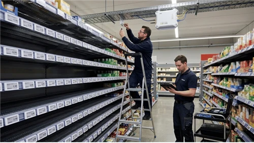
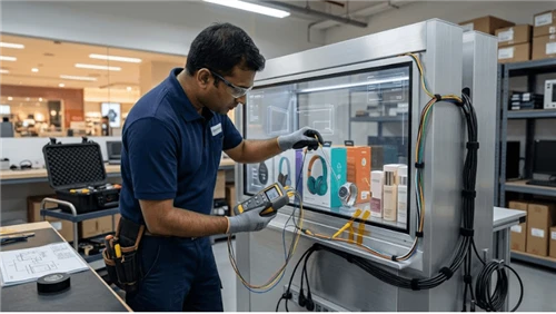
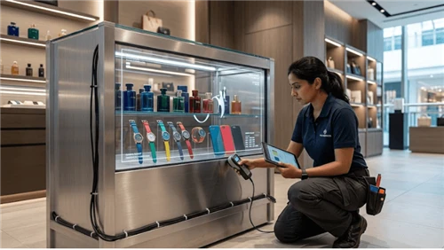
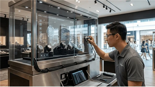
A Bar LCD screen can operate correctly on a bench and still develop mechanical faults after transport, installation, repeated shelf impacts, fixture movement, or long-term vibration.
The first symptom may not look mechanical. A display can shift slightly, a video connection can become intermittent, a power lead can move at its connector, or a cable can deteriorate at one repeatedly flexed point. The mounting screws may still be present even though the joint no longer retains the mechanical condition established during assembly.
For shelf applications such as stretched LCD displays used in supermarkets and grocery stores, the useful engineering model is the complete dynamic load path:
external vibration or impact → store fixture → rail → bracket → fastened joint → display chassis → internal modules → cables and connectors
Vibration and shock requirements must be tied to the production assembly and intended environment. There is no universal acceleration, frequency range, random-vibration PSD, shock pulse, test duration, fastener torque, or allowable post-test movement that applies to every Bar LCD installation.

Separate Sinusoidal Vibration, Random Vibration, Shock, and Transport Exposure
These mechanical inputs can reveal different weaknesses and should not be treated as interchangeable test names.
Sinusoidal vibration
Sinusoidal testing applies controlled vibration at defined frequencies and is useful for evaluating mechanical response, weakness, degradation, and dynamic behavior under a specified test program. IEC 60068-2-6:2007 provides the standardized Test Fc method for sinusoidal vibration. :contentReference[oaicite:7]{index=7}
Broadband random vibration
Random vibration represents a stochastic input rather than a single controlled sinusoidal frequency. IEC 60068-2-64:2008+A1:2019 covers broadband random vibration and specifically notes transportation and operational environments among its applications. :contentReference[oaicite:8]{index=8}
This distinction matters when a test objective involves logistics or another environment where vibration energy is distributed across a frequency band. It does not mean every shipped Bar LCD automatically requires the same random-vibration profile.
Shock
Shock is a transient mechanical event rather than continuing vibration. Examples can include handling impacts, an installed fixture being struck, or another project-specific event. IEC 60068-2-27:2008 provides a standardized shock-test procedure for specified repetitive or non-repetitive shocks. :contentReference[oaicite:9]{index=9}
Transport exposure
Transport testing includes the product, its support condition, and often its packaging system. The mechanical state of a packaged commercial LCD display may be completely different from the same unit bolted to a retail shelf.
The selected test method and severity should come from the intended environment, applicable specification, customer requirement, or qualified project test plan rather than from a copied Bar LCD value.
Map the Dynamic Load Path Through the Installed Bar LCD
Start with the complete mechanical structure rather than treating the LCD panel as an isolated specimen.
For a typical shelf-mounted unit, the path may be:
store fixture → rail → mounting bracket → fastener stack → display enclosure → internal frame
The response can change when any part of this chain changes.
Record the production configuration used for validation:
- display model and hardware revision;
- display mass and relevant center-of-gravity condition;
- shelf or rail construction;
- bracket revision;
- fastener specification;
- washers, spacers, inserts, or locking features;
- cable routing and strain relief;
- connector-retention hardware;
- internal player or controller mounting where applicable;
- shipping configuration when transport testing is included.
A compact product such as a 28-inch Bar LCD and a larger unit do not necessarily create the same bracket moment, center-of-gravity condition, rail response, or cable routing. Validation should follow the released mechanical configuration rather than the product category name alone.
Specimen mounting is itself part of dynamic testing. IEC 60068-2-47:2005 specifically addresses mounting packaged and unpackaged specimens for vibration, impact, and related dynamic tests. :contentReference[oaicite:10]{index=10}
A test on a very rigid laboratory plate does not by itself characterize the response of the same display on a flexible retail rail.

Control Fastener Preload Before Adding Locking Features
A bolted joint works by creating clamp load between the joined parts.
The important condition after assembly and dynamic exposure is not simply whether the screw remains physically present. The joint must continue to perform its intended clamping function under the loads defined for the project.
If the joint slips, separates, settles, or loses its intended mechanical condition, possible observations include:
- visible display rotation;
- bracket movement;
- fretting at contact surfaces;
- polished or enlarged holes;
- recurring alignment loss;
- additional cyclic loading on the fastener;
- movement transferred into cables or connectors.
NASA's Fastener Design Manual documentation covers locking methods, washers, threads, fatigue loading and fastener torque as related fastener-design subjects. These principles are useful background, but the approved fastener design for a Bar LCD still depends on its actual materials, geometry and load conditions. :contentReference[oaicite:11]{index=11}
Torque is an assembly control, not a universal pass number
Torque is commonly used to control fastener installation, but a value should not be copied from an unrelated bracket.
The required assembly condition can depend on:
- fastener diameter and material;
- thread engagement;
- joint material;
- friction and lubrication condition;
- washers or spacers;
- inserts;
- bracket thickness and stiffness;
- manufacturer requirements.
A torque requirement therefore belongs to the approved mechanical design and assembly procedure.
Locking methods are design-specific
Mechanical locking features, locking nuts, thread-locking systems, captive hardware, or other retention approaches may be used where appropriate to the joint.
They do not correct:
- insufficient thread engagement;
- a fastener that bottoms before developing the intended clamp condition;
- an underdesigned bracket;
- excessive joint movement;
- creep or settlement in soft joint materials;
- a distorted mounting surface.
This becomes particularly important in custom LCD retail-signage designs, where bracket geometry, inserts, enclosure materials and cable routing may differ from a standard product configuration.
Know What Fastener Inspection Evidence Actually Shows
Post-test fastener inspection should distinguish direct measurements from indirect indicators.
| Inspection evidence | What it can help show | Important limitation |
|---|---|---|
| Witness mark | Visible relative rotation or movement between marked parts | An unchanged mark is not a direct measurement of retained preload |
| Visual inspection | Fretting, deformation, polished contact areas, damaged threads, surface movement | May not reveal every change in joint force |
| Alignment or displacement measurement | Movement of the display, bracket, or joint relative to its reference | Does not directly quantify bolt preload |
| Post-test torque audit | Limited information about fastener rotational resistance under the defined method | Should not automatically be presented as a direct measurement of retained preload |
| Direct preload or bolt-load method | Fastener load where the joint design and measurement method support it | Requires an appropriate measurement technique and defined correlation |
The inspection plan should select evidence that matches the failure mechanism being investigated rather than relying on one universal fastener check.
Bracket Stiffness and Resonance Can Amplify Motion
A Bar LCD does not experience vibration independently of its bracket and fixture.
A long rail, thin mounting plate, cantilevered bracket, flexible shelf, or lightly supported fixture can have its own dynamic response. If the excitation coincides with a structural resonance, the response at the display can become substantially different from the input measured elsewhere in the structure.
Review:
- bracket stiffness;
- unsupported span;
- display mass;
- center-of-gravity offset;
- attachment locations;
- shelf loading;
- neighboring displays;
- fixture joints.
A longer unit such as a 43.9-inch Bar LCD can create a different structural arrangement from a shorter model even when both belong to the same display family. The relevant dynamic condition comes from the complete installation.
Confirm resonance with input and response measurements where needed
When resonance is suspected, the useful question is whether the display or bracket response changes significantly relative to the excitation applied to the fixture.
A project-specific investigation may use:
- controlled excitation;
- a measurement of the mechanical input;
- response measurement at a relevant bracket, rail, chassis, or display location;
- accelerometers or another suitable motion-measurement method;
- comparison of fixture response with display response;
- documentation of the frequency or condition associated with the observed response.
The sensor locations, excitation method and acceptance criteria must match the actual investigation. The article does not prescribe a universal resonance amplification limit.
If a bracket or fixture is modified to address dynamic response, mechanical alignment should be checked again before release, especially on long-form units such as a 49.5-inch Bar LCD.

Keep Cable Motion Away From Connectors and Repeated Bend Points
A cable can deteriorate even when its connector never completely disconnects.
Repeated movement can concentrate at:
- the connector exit;
- a cable tie;
- a sharp enclosure edge;
- the end of rigid conduit;
- a service loop that is too short for the required movement;
- an unsupported adapter or converter.
The connector should not become the structural support for cable mass or repeated cable motion.
Useful controls include:
- strain relief independent of the connector;
- sufficient service loop for intended movement and service access;
- support for heavy adapters or converters;
- bend-radius control appropriate to the cable;
- routing that prevents rubbing against sharp or moving structure;
- retention that does not create another concentrated flex point.
This is particularly relevant when the screen is part of a broader smart LCD integration containing media players, controllers, adapters, networking hardware, sensors, or other locally mounted electronics.
When image or power loss appears only while the shelf or fixture moves, cable motion and connector loading should be investigated before assuming that the LCD panel itself has failed.
Inspect Internal Supports and Modules That Can Move
The external bracket can remain secure while an internal component or locally integrated module moves.
Depending on the product architecture, relevant items can include:
- controller boards;
- power boards;
- media players;
- internal harnesses;
- terminal blocks;
- adapters;
- speakers;
- power supplies;
- removable service modules.
A module retained to the chassis creates a different mechanical condition from the same component supported primarily by an electrical connector or unsupported cable.
Internal harnesses should also be checked for repeated flexing, rubbing and contact with sharp sheet-metal features where the product can be inspected under its approved service procedure.
Do not open or modify equipment outside the applicable service or design procedure. Internal-support requirements must follow the actual product architecture and the requirements of the selected commercial-grade LCD configuration.
Do Not Use a Shipping Test as Proof of the Installed Shelf Condition
Packaging changes the mechanical boundary conditions.
During shipping, a Bar LCD may be:
- supported by foam;
- constrained inside a carton;
- isolated from its retail mounting bracket;
- protected by temporary transport restraints.
After installation, it may instead be:
- bolted to a long shelf rail;
- cantilevered from a bracket;
- connected to several cables;
- mechanically coupled to neighboring displays.
Consequently, packaged transport validation and installed-use validation answer different questions.
The hardware architecture should also be frozen before assuming that results transfer between display technologies. Projects still selecting the physical platform can review the differences between LCD bar screens and LED bar screens separately from the dynamic test program.
Define the Dynamic Test Before Running It
A reproducible vibration or shock test starts with a clear record of the condition being qualified.
| Test field | What to record |
|---|---|
| Environment represented | Transport, installed operation, handling, service event, or another defined condition |
| Mechanical input | Sinusoidal vibration, broadband random vibration, shock, or another project-defined input |
| Specimen condition | Packaged or unpackaged |
| Operating state | Operating, standby, or non-operating as required by the test objective |
| Mounting | Production bracket, representative rail, package support, or defined test fixture |
| Orientation / axes | Project-defined test orientations and axes |
| Input measurement | Location and method used to characterize the applied mechanical input |
| Response measurement | Relevant fixture, bracket, chassis, or display location where required |
| Functions monitored | Video, power, communication, player status, or other relevant functions |
| Pre-test condition | Alignment, bracket, fasteners, cables, connectors and functional state |
| Post-test condition | Repeatable inspection of the same mechanical and functional items |
| Acceptance requirement | Project-specific functional and mechanical pass/fail conditions |
The test fixture deserves explicit documentation. A fixture much stiffer than the final shelf can suppress a response that exists in production, while an unsuitable flexible fixture can create a response that is not representative of the installation.
This is also why testing should use the actual intended product topology. A shelf run based on a 49-inch Bar LCD display should not inherit a dynamic validation record from another size or bracket without checking the changed load path.
Measure Before and After Dynamic Exposure
A dynamic test becomes much more useful when the pre-test mechanical state has been documented.
| Inspection item | Example evidence |
|---|---|
| Display position | Reference dimensions or alignment measurement |
| Bracket condition | Photographs and drawing revision |
| Fastener installation | Approved hardware, assembly record and relevant inspection marks |
| Cable routing | Photographs, support points and strain-relief locations |
| Connector state | Visual or project-defined retention inspection |
| Functional state | Image, power, communication and player status as applicable |
| Internal modules where serviceable | Mounting and harness condition |
During the test, monitor functions that can reveal intermittent dynamic faults where the setup permits it.
After exposure, inspect specifically for:
- display shift or rotation;
- fastener or bracket movement;
- changed witness marks;
- fretting or polished contact surfaces;
- elongated holes;
- bracket deformation;
- cable migration;
- damaged cable jackets;
- connector movement;
- intermittent image or power faults;
- abnormal mechanical noise;
- internal module movement where inspectable.
A retail-oriented product may still show an apparently normal advertising image while mechanical evidence has changed. This is why functional inspection should accompany, rather than replace, mechanical inspection in LCD advertising display applications.

Troubleshoot Dynamic Mechanical Problems by Symptom
| Symptom | First area to investigate |
|---|---|
| Display is visibly rotated after an impact | Bracket movement, joint slip, fastener condition |
| Alignment gradually changes during operation | Preload retention, fixture movement, recurring excitation |
| Image drops only while the fixture moves | Cable flex, connector loading, internal harness |
| Fault appears after shipping but was absent before shipment | Packaging condition, shock/vibration exposure, connectors and internal supports |
| Fasteners remain installed but witness marks have moved | Relative joint movement, rotation or slip |
| Cable jacket shows wear at one location | Concentrated flexing or rubbing |
| One shelf/fixture type repeatedly develops faults | Fixture stiffness, resonance and mounting geometry |
| A replacement display behaves differently | Mass, center of gravity, hardware revision, bracket compatibility and cable routing |
| Unit passes on a rigid bench but fails when installed | Production rail or bracket dynamic response |
Preserve the failed mechanical state before tightening hardware or rerouting cables. Movement, contact marks and cable position can contain useful evidence that disappears after repair.
Retest After Changes to the Mechanical Load Path
Repeat the affected dynamic checks when a change can alter how vibration or shock reaches the display.
Relevant changes include:
- display model or hardware revision;
- display mass or center of gravity;
- bracket design;
- shelf or rail construction;
- fastener specification;
- locking method;
- washer, spacer or insert;
- cable type or routing;
- strain relief;
- connector-retention hardware;
- internal player or module;
- transport packaging;
- service procedure that changes mechanical assembly.
A software-only change normally does not justify a mechanical vibration retest unless it changes the tested operating state or another condition relevant to the dynamic requirement.
Hardware selection should therefore be stabilized before final mechanical qualification. The Bar LCD display buying guide can be used earlier in the project to resolve format and application requirements before the production dynamic test configuration is frozen.
Bar LCD Vibration and Shock Checklist
- Separate sinusoidal vibration, random vibration, shock and transport requirements.
- Document the complete production dynamic load path.
- Identify the actual shelf, rail, bracket and fastener stack.
- Base fastener assembly requirements on the approved joint design.
- Do not use locking features as a substitute for inadequate joint mechanics.
- Consider bracket stiffness and possible structural resonance.
- Measure input and response where resonance confirmation is required.
- Control cable motion independently of connector retention.
- Avoid concentrated bend points and cable rubbing.
- Support internal modules appropriately for the product architecture.
- Keep packaged-product and installed-use validation separate.
- Document specimen and test-fixture mounting.
- Record the mechanical baseline before dynamic exposure.
- Monitor relevant functions during testing where practical.
- Inspect alignment, fasteners, cables, connectors and supports after exposure.
- Interpret witness marks and torque checks within their actual evidence limits.
- Repeat affected tests after a change to the dynamic load path.
The objective is not simply to confirm that every screw remains visible after a test. The released mechanical system must preserve the geometry, joint condition, cable support, connector state and functional behavior required by the actual installation.
Teams evaluating a new deployment can review the wider LCD display range and define the final screen, bracket, fixture, player and cable architecture before freezing the vibration or shock test configuration.
For a custom Bar LCD project, provide the display size, quantity, shelf or rail construction, bracket concept, mounting orientation, transport environment, installed vibration or shock requirement, cable architecture and required mechanical evidence when you request a project-specific quotation.